Prime contractors Thales Alenia Space and Airbus Defense and Space have jointly selected, along with the European Space Agency (ESA), Snecma’s PPS 5000 plasma (electric) thruster for their new-generation telecommunications satellite platforms.
The Neosat program includes the delivery, in the summer of 2017, of complete shipsets of plasma thrusters, along with design studies and testing, for the two prime contractors’ respective platforms, the Eurostar Neo from Airbus Defense and Space, and the Spacebus Neo from Thales Alenia Space. These two platforms will be optimized for all-electric propulsion systems, used to raise the satellite into its definitive orbit after release from the launcher, and to keep it in its assigned operational orbit (stationkeeping). The total market will include more than 350 thrusters to be supplied by Snecma.
ESA’s Neosat program is being conducted in collaboration with a number of space agencies from European countries, in particular French space agency CNES. The aim is to develop and qualify a family of robust, modular platforms that will meet the needs of telecom satellite operators. This program is targeting a 30% reduction in satellite costs versus current models by 2020, while also winning 50% of the telecom satellite market during the period 2018-2030.
Vernon, France-based Snecma, a division of France’s Safran aero-engine manufacturer, has been working on plasma-electric satellite thrusters for 20 years, starting with a collaboration with Russia’s OKB Fakel, a pioneer in the use of electric propulsion as a lighter-weight alternative to chemical propellant for telecommunications satellites.
The French space agency, CNES, has used a public bond fund to help finance a made-in-France thruster, and the 22-nation European Space Agency has also contributed funding as part of the Neosat program to build next-generation telecommunications satellites. CNES invested 25 million euros ($27 million) in the PPS 5000 program in early 2015 and said additional funding would follow to support in-orbit validation of the technology.
Neosat is designed to give both Airbus Defence and Space and Thales Alenia Space new-generation satellite platforms, including electric propulsion, to sharpen their competitive edge against current and future competitors in the United States, Japan, China and elsewhere. Satellite fleet operator Eutelsat of Paris has agreed to be the first commercial operator to fly the PPS 5000, on the 172B satellite to be launched in 2017. It will be the first European-built satellite to rely on electric propulsion for both in-orbit station-keeping and orbit-raising after separation from its launch vehicle. The launch, aboard a European Ariane 5 rocket, is the beneficiary of government support to carry the PPS 5000 program through to commercial demonstration.
Airbus and Thales Alenia Space have promised a 30 percent reduction in overall telecommunications satellite costs by 2020 once they have fully integrated the different Neo program elements into their production lines. The PPS 5000 is just one of the Neo elements. Electric propulsion saves up to 40 percent of a satellite’s launch weight for the same in-orbit capability, allowing satellite owners to load more payload onto a given platform or pocket the savings by selecting a smaller, less-costly rocket.
But an all-electric satellite will take months, not days, to climb from its transfer orbit to final geostationary position 36,000 kilometers over the equator. That delays revenue and is one reason why satellite builders are seeking electric propulsion options that reduce the time to final orbital position.
How it works
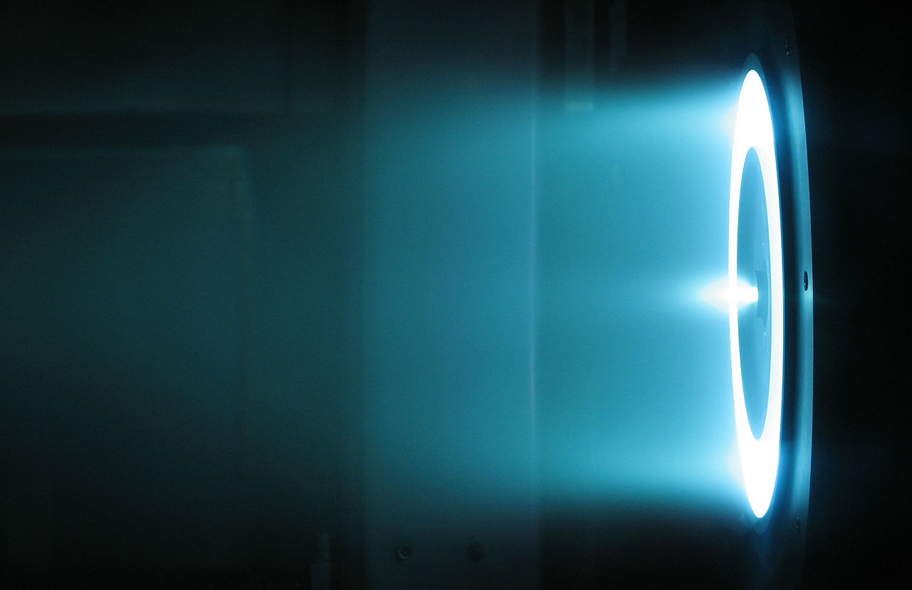
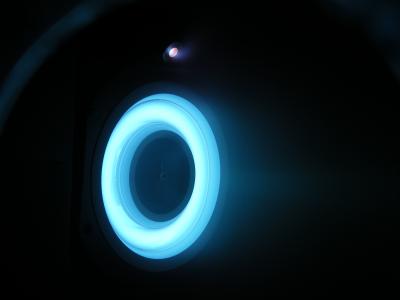
The essential working principle of the Hall thruster is that it uses an electrostatic potential to accelerate ions up to high speeds. In a Hall thruster the attractive negative charge is provided by an electron plasma at the open end of the thruster instead of a grid. A radial magnetic field of about 100–300 G (0.01–0.03 T) is used to confine the electrons, where the combination of the radial magnetic field and axial electric field cause the electrons to drift azimuthally thus forming the Hall current from which the device gets its name.
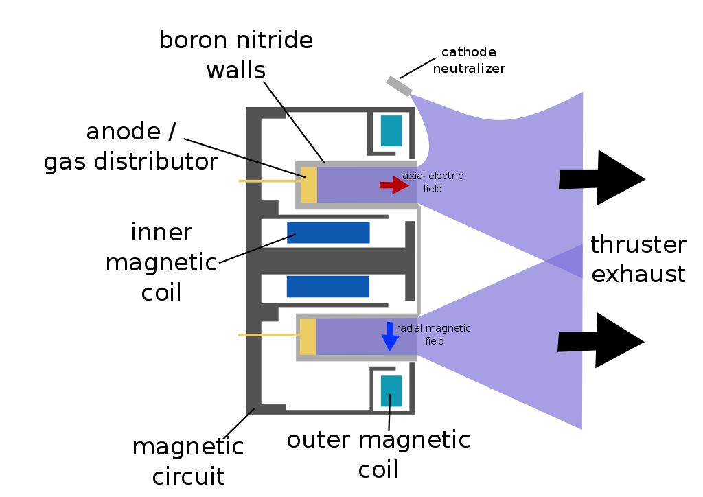
Hall thruster. Hall thrusters are largely axially symmetric. This is a cross-section containing that axis. A schematic of a Hall thruster is shown in the image to the right. An electric potential between 150 and 800 volts is applied between the anode andcathode.
The central spike forms one pole of an electromagnet and is surrounded by an annular space, and around that is the other pole of the electromagnet, with a radial magnetic field in between.
The propellant, such as xenon gas, is fed through the anode, which has numerous small holes in it to act as a gas distributor. Xenon propellant is used because of its high atomic weight and low ionization potential. As the neutral xenon atoms diffuse into the channel of the thruster, they are ionized by collisions with circulating high-energy electrons (typically 10–40 eV, or about 10% of the discharge voltage). Once ionized, the xenon ions typically have a charge of +1, though a small fraction (~20%) have +2.
The xenon ions are then accelerated by the electric field between the anode and the cathode. For discharge voltages of 300 V, the ions reach speeds of around 15 km/s (9.3 mps) for a specific impulse of 1,500 seconds (15 kN·s/kg). Upon exiting, however, the ions pull an equal number of electrons with them, creating a plasma plume with no net charge.
The radial magnetic field is designed to be strong enough to substantially deflect the low-mass electrons, but not the high-mass ions, which have a much larger gyroradius and are hardly impeded. The majority of electrons are thus stuck orbiting in the region of high radial magnetic field near the thruster exit plane, trapped in E×B (axial electric field and radial magnetic field). This orbital rotation of the electrons is a circulating Hall current, and it is from this that the Hall thruster gets its name. Collisions with other particles and walls, as well as plasma instabilities, allow some of the electrons to be freed from the magnetic field, and they drift towards the anode.
About 20–30% of the discharge current is an electron current, which does not produce thrust, thus limiting the energetic efficiency of the thruster; the other 70–80% of the current is in the ions. Because the majority of electrons are trapped in the Hall current, they have a long residence time inside the thruster and are able to ionize almost all of the xenon propellant, allowing mass utilizations of 90–99%. The mass utilization efficiency of the thruster is thus around 90%, while the discharge current efficiency is around 70%, for a combined thruster efficiency of around 63% (= 90% × 70%). Modern Hall thrusters have achieved efficiencies as high as 75% through advanced designs.
Compared to chemical rockets, the thrust is very small, on the order of 83 mN for a typical thruster operating at 300 V, 1.5 kW. For comparison, the weight of a coin like the U.S. quarter or a 20-cent Euro coin is approximately 60 mN. As with all forms of electrically powered spacecraft propulsion, thrust is limited by available power, efficiency, and specific impulse.
However, Hall thrusters operate at the high specific impulses that is typical for electric propulsion. One particular advantage of Hall thrusters, as compared to a gridded ion thruster, is that the generation and acceleration of the ions takes place in a quasi-neutral plasma, so there is no Child-Langmuir charge (space charge) saturated current limitation on the thrust density. This allows much smaller thrusters compared to gridded ion thrusters. Another advantage is that these thrusters can use a wider variety of propellants supplied to the anode, even oxygen, although something easily ionized is needed at the cathode.
Cylindrical Hall thrusters
Although conventional (annular) Hall thrusters are efficient in the kilowatt power regime, they become inefficient when scaled to small sizes. This is due to the difficulties associated with holding the performance scaling parameters constant while decreasing the channel size and increasing the applied magnetic field strength. This led to the design of the cylindrical Hall thruster. The cylindrical Hall thruster can be more readily scaled to smaller sizes due to its nonconventional discharge-chamber geometry and associated magnetic field profile. The cylindrical Hall thruster more readily lends itself to miniaturization and low-power operation than a conventional (annular) Hall thruster. The primary reason for cylindrical Hall thrusters is that it is difficult to achieve a regular Hall thruster that operates over a broad envelope from ~1 kW down to ~100 W while maintaining an efficiency of 45-55%.
Applications
Hall thrusters have been flying in space since December 1971 when the Soviets launched an SPT-50 on a Meteor satellite. Over 240 thrusters have flown in space since that time with a 100% success rate. Hall thrusters are now routinely flown on commercial GEO communications satellites where they are used for orbital insertion and stationkeeping.
The first Hall thruster to fly on a western satellite was a Russian D-55 built by TsNIIMASH, on the NRO’s STEX spacecraft, launched on October 3, 1998.
The solar electric propulsion system of the European Space Agency‘s SMART-1 spacecraft used a Snecma PPS-1350-G Hall thruster. SMART-1 was a technology demonstration mission that orbited the Moon. This use of the PPS-1350-G, starting on September 28, 2003, was the first use of a Hall thruster outside geosynchronous earth orbit (GEO). Unlike most Hall thruster propulsion systems used in commercial applications, the Hall thruster on SMART-1 could be throttled over a range of power, specific impulse, and thrust.
- Discharge power: 0.46–1.19 kW
- Specific impulse: 1,100–1,600 s
- Thrust: 30–70 mN