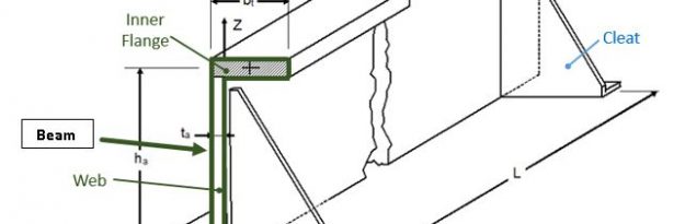
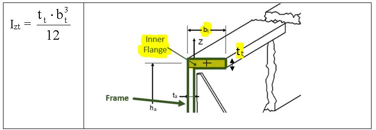
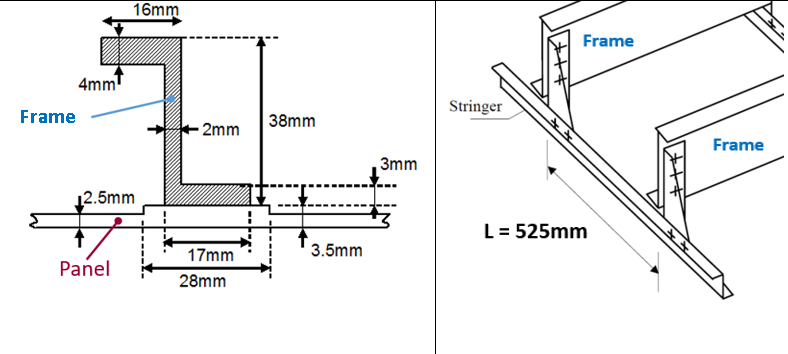
Lateral stability is commonly provided for a beam, a column, or a wall with lateral bracing. Lateral bracing is the structural component that prevents the beam or column from twisting or buckling sideways. Lateral instability is a result of inadequate lateral stability that is the property of an object to develop forces or to have forces imposed upon it that restore it to or maintain its original condition (position). A laterally unstable structure or structural member is able to twist, buckle sideways, or fall over. In the scheme below is shown a typical assembly of a fuselage Frame (that is made up by Inner Flange, Outer flange, Web) of plane, attached to a Panel, between two stabilizers (Cleats). If the Inner Flange of Frame is under the compressive load that it undergoes buckles, it is likely to involve the whole Frame in its deformation. The Cleats are used to minimize the lateral instability and to join the Frame to the panel.
- Equivalent Elasticity
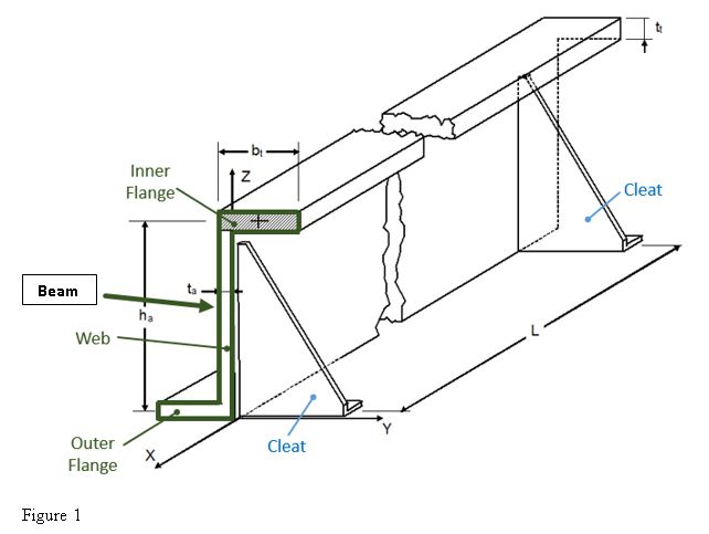
We assume that the Inner Flange of the Frame behaves like a bi-hinged beam at the level of the stabilizers (Cleats). The Cleats are considered as constraints with certain stiffness.
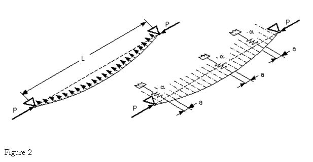
The bending stiffness (around X axis) can be calculated by the following formula:
Where:
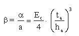
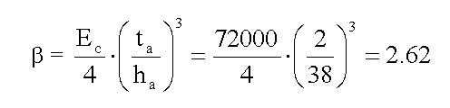
– α : is the elastic constant of the equivalent discrete supports (see Figure 2)
– IX_WEB : inertia of Web (see Figure 1) around the X axis.
– ta : thickness of web (see Figure 1)
– Ec: Young module in compression
– ha: height of frame’s web
– a: distance separating two equivalent discrete supports (see Figure 2)
The translational stiffness at the level of the Inner Flange is:
- Instability Stress (Linear Elastic)
The energy method allows us to determine the critical buckling load (see “Theory of elastic stability” by TIMOSHENKO/GERE, paragraph 2.10) by considering the deformation of the elastic line as a sinusoidal series with a wave node at each end of it (the ends are the level of the stabilizers/Cleat).
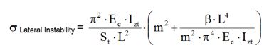
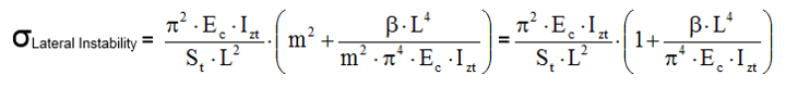
By minimizing this deformation energy, the lowest critical buckling stress (linear elasticity) is obtained, which is:
with:
• Ec: modulus of elasticity (Compression) of the stiffener
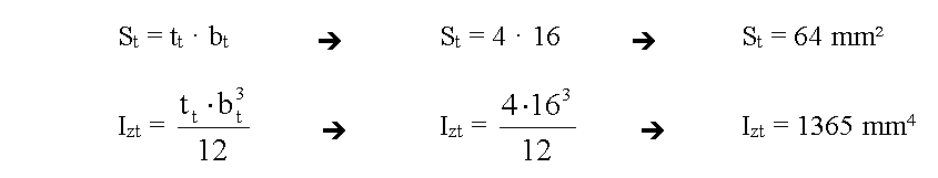
• IZt: minimum inertia of the Inner Flange section
• St: area of the Inner Flange section
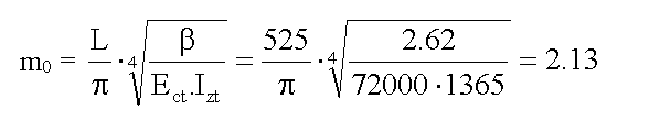
• L: distance between Stabilizers/Cleats
• m: number of half-wavelengths
• β: translational stiffness at the level of the Inner Flange
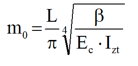
The parameter “m” (number of half-wavelengths) is an integer, greater than or equal to 1, and it depends to the fact that the stabilizers are located at wave nodes by assumption. This number of half-wavelengths “m” into which the bar is subdivided at buckling, can be calculated by imposing condition that the above expression is minimum (making a derivate with respect the parameter “m”). The parameter IZt is the minimum inertia of the Inner Flange with respect to the Z axis passing through the CoG (center of gravity) of the Inner Flange section, and it can be calculated as follows:
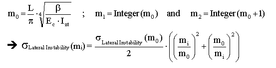
- Determination of m0 by minimizing ”σLateral Instability”
In order to minimize σLateral Instability it is necessary to determine “m” as following:
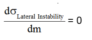
Determination of “m” giving the lowest of the values of σLateral Instability :
With:
• Ec: modulus of elasticity in compression of the stiffener;
• IZt: Inertia of the Inner Flange with respect to the Z axis;
• L: length of the beam modeling between stabilizers;
• m0: number of half-wavelengths. This number is always greater than 1;
• β : translational stiffness at the level of the Inner Flange
The value of “m0” determined by the equation reported above, could be not be an integer. But it is necessary to have an integer value of “m” to have a wave node at level of the stabilizers. Thus the calculation of σLateral Instability is carried out considering the two closest integer values framing the calculated “m”, and it will be accounted the value of “m” which gives the minimum value of σLateral Instability.
The allowable σLateral Instability calculated with m0≥1 is the buckling stress when the stabilizers are infinitely far each other.
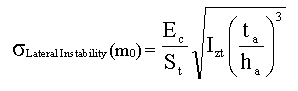
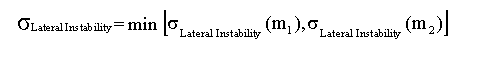
If σLateral Instability (Integer(m0)) > σLateral Instability (Integer (m0 + 1)), then we must take m = Integer (m0 + 1), else m = Integer(m0), with Integer (m0) = integer part of m0. If 1>m0 then we will use the previous equation by taking m=1:
Therefore the final equations to consider for the calculation of σLateral Instability are:
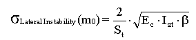
with:
Then we will calculate the critical stress as follows:
- Plasticity Correction
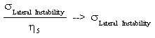
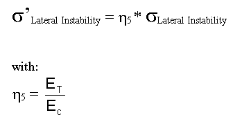
If the value of Afe6eσLateral Instability is higher than 0.5 · Fcy, than it is necessary to consider the effect of plasticity of material by the coefficient η5 :
σ’Lateral Instability = η5 * σLateral Instability
The calculation is iterative because η5 = f (ET,v) = g(σLateral Instability).
The convergence is reached when:
The plasticity coefficient is calculated as the ratio between ET and EC:

With:
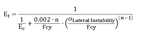
- ET is the tangent module, calculated as following:
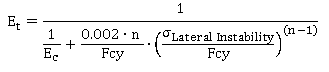
- EC is the Young compression module
In the conception phase, we will make sure to have σLateral Instability ≥ Fcy, in order to use Fcy.
- Numerical Example
Given the following assembly (made up by a Frame and a Panel), calculate the maximum allowable for the lateral Instability.
| Material : 7175 T7351 | |
| Tension allowable: | Ftu = 425 MPa |
| Compression allowable: | Fcy = 415 MPa |
| Young module(Compression) | Ec = 72000 MPa |
| Ramberg Osgood coefficient | n = 11 |
Inter-Frame distance is: L=525mm
Step 1: Calculation of St and IZt
Step 2: Calculation of β
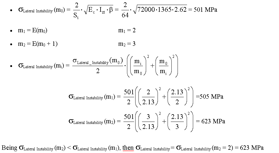
Step 3: Calculation of mo
Step 4: Calculation of Critical Stress
Step 5: Plasticity Correction
If σLateral Instability≤ Fcy / 2 then ET= EC , otherwise:
In this case σLateral Instability= 623 MPa > Fcy / 2 = 208 MPa.
To determine the corrected critical stress, the following equation must be solved numerically:
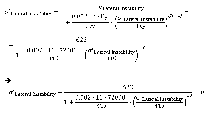
In order to obtain the equivalence reported above, you have to carry out a numerical iteration; it can be done easily by “Goal Seek” function of Microsoft Excel, see below how:

Set the following parameters (see figure below):
“Set cell” = equation reported above
“To value” = 0
“By changing cell” = link to cell to cell where you set an initial value for σ’Lateral Instability (for example to 200 MPa)
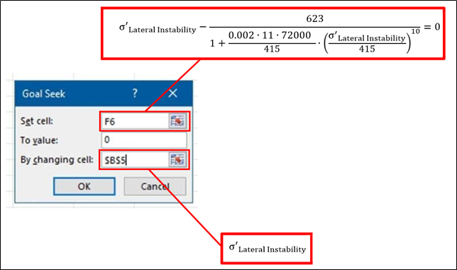
Then click on “OK”, and you will get the final value for the allowable:
σ’Lateral Instability = 353.3 MPa