Today, electromagnetic propulsion (EMP) for submarines — a propellerless and therefore silent and maintenance-free way to drive a craft through water — is getting new attention. A hypothetical design for a 15-ton sub using this form of propulsion was presented at the recent SAE meeting in Detroit by Dr Stewart Way of Westinghouse R&D Center, Pittsburgh. According to Dr Way, a Russian inventor has already begun to test a prototype like the on Way suggests, and engineers at the Israel Institute of Technology, Haifa, indicate an intention of soon building a similar prototype of their own.
Repulsive Principle ~
Way tested the first prototype, a 10-ft model, more than two years ago (Prod. Engg., September 12, 1966, p. 39). Since then, he a others have worked, off and on, to explore the idea. The US Navy had been keenly interested in the concept from 1958 to 1961 but had found the outlook poor for practical application of the theory.
Latest in superconducting magnet technology may have changed that outlook, Dr Way believes, by greatly increasing the power plant’s efficiency.
The “solid-state” propulsion principle is as simple as high school physics. If a wire is placed between the poles of a “U” magnet and current is passed through the wire, the wire jumps away from the magnet, in response to Lorentz forces. Make a submarine the magnet and the surrounding water the wire, and you have an underwater vessel with a no-moving-parts propulsion system.
Super Magnets for Super Subs ~
For his 15-ton vessel, about 24 feet long, Dr Way concludes that two tons of batteries could furnish enough energy to drive the current through sea water. Reaction with a superconducting magnet aboard the craft could propel the submarine at about 6 knots. And the 2-man vessel could cruise more than 9 hours at a time, Way says.
Way’s 10ft earlier prototype weighed 900 lb and had 300 lb of batteries, which had to be recharged after about 15 min. It had a conventional rather than superconducting magnet, and its top speed was only about ½ knot.
The researcher says the advent of the practical superconducting magnet, which draws no power on board, had vastly increased an EMP craft’s potential range and speed. He suggests that someday mammoth EMP cargo submarines with displacements of 1`00,000 tons may be hauling freight silently through the ocean depths at speeds up to 25 knots. The energy for generating the current around these supersubs would come from nuclear power plants.
Feasible Today?
Right now, EMP may be highly suited to small research submarines, Dr Way says, and he would like to see a full-scale prototype developed in this country for practical evaluation.
Silence of operation would mean research subs could literally sneak up on fish. Water around them would not be agitated, and ocean-bottom materials wouldn’t be stirred up. Dr Way estimates tht overall disturbance of the ocean would be reduced 90%. A small electromagnetic force would be acting over a large area, rather than a large physical force acting over a very small area, as with a propeller.
Other Advantages ~
In addition, an EMP sub would be more maneuverable than a conventionally propelled craft. At slow forward speeds, conventional submarines don’t respond well to lateral or yaw changes of direction. Auxiliary propellers to correct this deficiency only add to ocean disturbance. An EMP sub could easily be designed to provide lateral and turning forces as well as “fine control” of elevation.
Dr Way also suggests it may be possible to reduce hull drag by using the Lorentz force s on the wter that surrounds the hull, though he didn’t consider this effect in his design.
Design Considerations ~
To be sure, the designer of a working EMP sub would face some problems. To begin with, the external magnetic field would attract metal objects on the ocean floor (treasure hunters might consider this a boon). Dr Way judges that his 15-ton model would have to steer clear of iron objects by at least 5 ft, else it might have to deenergize its superconducting magnet in order to get free.
The crew’s proximity to magnetic fields inside the sub is another problem. But Dr Way reasons it can be solved by placing the field coil slightly aft and the crew well forward, with an iron shield between.
Also, liquid helium would have to be circulated around the superconducting magnet to maintain it at cryogenic temperature. But Dr Way thinks an on-board refrigeration plant would not be necessary; the rate at which the helium would boil off is not excessive. However, the lost helium would have to be replenished periodically.
Discover Magazine (May, 1980s, Date/Author Unknown)
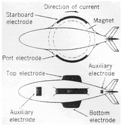
Anyone who has played with magnets knows it is possible to push one magnet along by forcing the north or south pole of another close to the same pole of the first. Such a magnetic shove wouldn’t be a bad form of propulsion if there were a way to keep it going. In fact, some Japanese scientists are trying to propel ships using this principle — but instead of forcing actual magnets close to the ones built into their ships, they continually generate repulsing magnetic fields in the surround seawater to push vessels along. Yoshiro Saji and his colleagues at the Kobe University of Mercantile Marine in Kobe, Japan, are convinced that their method of electromagnetic propulsion has the potential to provide more efficient, faster way of powering even large tankers.
Saji begins with a large electromagnet mounted along the ship’s sides. An electric current from on-board generators is then passed from one side of the ship to the other through conductive seawater, creating a magnetic force that pushes against the ship’s magnet. The seawater is driven backwards, and the ship is pushed forward, As the ship moves ahead, a current continually flows through a constant repulsive field to drive it onward, In a sense the ship is lifting itself by its own bootstraps.
The idea of electromagnetic propulsion was first developed in the 1950s primarily by Stewart Way, then a consultant for Westinghouse Electric Corporation. He wanted to use it for submarines, since at the higher speeds promised by electromagnetic propulsion it would make them faster than surface vessels, which are hindered by waves. In 1968 Way constructed a 10-ft working model of an electromagnetically propelled submarine using conventional magnets. But a full-scale version of his test vessel would have required magnets weighing 500,000 tons — about 80 times the total weight of a Polaris submarine. Lightweight superconducting magnets could have solved the weight problem, but at the time they were prohibitively expensive to operate. Work on electromagnetic propulsion the US came to a standstill.
Saji’s recent work in Japan followed the development of highly efficient niobium-titanium superconductors, cooled by liquid helium to a temperature of -550 F. Armed with these new materials, his group has built two experimental scale models that he says prove the feasibility of EM propulsion. The second and larger model is nearly 12 ft long, weighs 1650 lb, and has a superconducting magnet with a field 60,000 times stronger than the Earth’s natural field. Experiments have shown that it can travel about 1.5 miles per hour.
Extrapolating from his studies, Saji believes that a full-scale, 10,000-ton submarine tanker can achieve a top speed of 100 knots, or 115 mph; the fastest submarines, now limited by water resistance to the screw propeller, cannot exceed 70 knots, or 81 mph. Today’s surface vessels, because of wave drag, are much slower. Saji estimates the cost of building the sub would be comparable to the cost of a conventional tanker of the same size. And he predicts that the sub’s demand for fuel — to deed the onboard generator that powers the electromagnet and the seawater current — would be less than the fuel needs of a traditional tanker.
Although there are no current plans to put Saji’s studies to practical use, the principles of EM propulsion have other potential application.
Yoshiro SAJI ~ Japan Patent JP 61-188297
Propulsion System
Warren A. Rice
The present invention relates to a propulsion system for vessels traveling in an ionic media and more particularly relates to drive systems wherein the outer surface of the vessel constitutes an electrolytic cell employing the ambient ionic media as an operating electrolyte. Still more particularly the present invention relates to a vessel propulsion drive requiring no moving parts and wherein the thrust is accomplished electromagnetically to promote laminar fluid flow at the interphase between vessel and media.
The instant drive or propulsion system is applicable to all vessels, such as ships, submarines, torpedoes, and the like traveling in salt water. Insofar as can be experimentally shown the device also has utility as a space drive system for imparting thrust to a vessel traveling in an ionic atmosphere, for example, space.
It has long been known that when an electrical current is passed through a magnetic field that a thrust is accomplished which obeys the “left hand rule” and which is of a magnitude directly proportional to the magnetic field strength and the current density. Such electrical principles are applied in electromagnetic pumps for the handling, for example, of liquid material which is an electrolyte. Such a device is illustrated in US Patent # 2,786,416 issued to Alan Fenemore (March 26, 1957).
Similarly, particle acceleration in vacuum tubes has demonstrated the concept of thrust obtained by intersecting lines of magnetic flux with a suitable current flow in an ionic atmosphere. Reference is made to US Patent # 2,397,891 to Donald Kerst (Februarry 21, 1950).
However, until the instant invention there was no appreciation of the application of the known principles to the problem of propelling a vessel in an electrolyte and space.
It has now been found that the structural members of the vessel itself can be utilized to generate a thrust of sufficient magnitude to be useful. It has also been found that the flow obtained at the interphase between hull and fluid media is substantially laminar so as to impart an added credit to the concept of vessel propulsion by material reduction in friction.
Thus, the hull itself generates the force to propel the vessel and the hull form imparts direct surface thrust in contrast, for example, to prior art propeller propulsion and its accompanying turbulent flow.
Accordingly one of the objects is to provide a propulsion means integrated into the hull structure of the vessel to be propelled.
Still another object is to provide a hull surface capable of serving as a cell in an ionic media so as to provide desired EM force.
Other objects include the provision of a highly efficient propulsion means eliminating the necessity for intricate mechanical movements extending into the liquid media to require intricate and expensive seal means. These objects include obvious design simplification which can result from the adoption of the presently described propulsion means.
In the drawings:
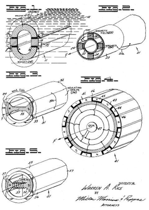
Figure 2 is a perspective schematic view of a tube encasing, for example, the hull or shell of a projectile, vessel, or the like where the EMF is generated by the cell established by the silver hull and the magnesium sleeve and where the magnetic flux lines are available from permanent magnets used as spacers.
Figure 3 is a schematic view of a device which also utilizes a cell created by structural portions of the hull separated by suitable insulating strips and having a permanent magnet internally oriented so as to establish magnetic flux lines intersectable by the EMF established by the cell in the electrolyte to provide a thrust force in the direction indicated.
Figure 4 illustrates a hull structure in schematic cross section indicating a segmentalized external system of alternate N and S magnetic poles supplied with an EMF from a suitable generator and being conducted by the electrolyte or ionic media in which the hull is immersed.
Figure 5 illustrates in schematic perspective a system in accord with the present invention whereby the hull establishes an electrolytic cell and the magnetic flux density is obtained by the use of a generator-served electromagnet.
General Description ~
In electromagnetic phenomena it has long been known that if a current is passed across a magnetic field a force is set up which generally is dependent upon the flux D, the distance between conductors, and the amperage or current. The general formula may be expressed as:
Thrust in kilograms = (10.2 x 10⁻⁸ [flux density (gauss) x d (centimeters) x I (amperes)]
Conversion to pounds of thrust is accomplished by multiplying the thrust in kilograms b the rough factor of 2.2.
Experimental work based on this data has generally validated this above expression and supplementally has shown that the thrust is a reaction to the movement of the electrolyte through which the current passes. Viewed in a vacuum the thrust may be expressed in terms of ionic drive employing beta particle emission with the bonus obtained by appreciation of mass. Further, the flow pattern appears “laminar” in nature in contrast to a type of thrust imparted by a driven propeller, the latter being characterized as “turbulent”. Peculiarly the laminar flow is substantially independent of hull design, that is, the hull design becomes considerably less critical assuming that the entire hull is used as a drive fixture.
In general a magnetic field is established using components of the vessel as alternate N and S poles. As between these structurally established poles a magnetic flux is established through an ionic media, for example, an ionized atmosphere such as space or an electrolyte such as salt water. An electric current, also emanating from the structural members of the vessel passes through the ionic media cutting the magnetic lines of force. The result is a movement of the electrolyte in obedience to the “right hand rule”. The movement is equivalent to the force exerted in accord with the foregoing general formulation and a reaction force thus propels the vessel.
When the above expression is applied in space it can be said that hull members provide the magnetic field and that hull members also serve the function of anode and cathode for current flow in an ionic media. However, in the case of space the electron flow is established by the system and the particle emission comprises beta particles which appreciate in mass as they approach the speed of light. Thus, it is felt that some correction in value of the total thrust should be applied in the instance of an application to space versus the situation existing for propulsion in an electrolyte.
In sopme instances the source of EM force may be cell-derived in which instance the hull of the craft, or portions thereof comprise a single cell or a plurality of cells where the latter is advantageous. Where this cell system is desirable permanent magnets establish the required magnetic field.
It will be appreciated that an electric generator within the craft may also supply EM force to the anode and cathode members of the structure and provide an electromagnet with current for the establishment of magnetic flux lines of desired magnitude.
Similarly, the scope of the contribution to embrace combinations of cell, magnet, and mechanically generated source of EM force wherein the magnetic poles and the cathode and anode elements comprise a structural adjunct to the vessel hull. Inasmuch as the current must pass through a magnetic field in an ionic media, a simple form of the device is annular where the annulus is immersible in the ionic media.
Specific Description ~
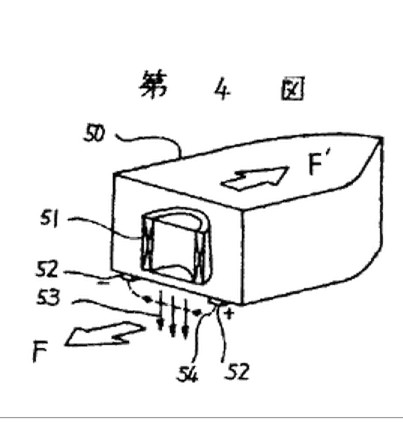
The invention may be better appreciated by reference to the accompanying drawings. With reference to Figure 1, an annular form of enclosure or hull 11 is illustrated. Thus, the hull 11 is tubular in character and is immersed in an ionic media 12, for example salt water or ionic space. Magnets 13 and 4, comprising elements of the hull 11, establish a magnetic field 15 bridging the gap shown. Insulators 16, space the magnets 13 and 14 from closed contact with each other. An anode 17 and cathode 18 are positioned between the magnets 13 and 14. The anodes 17 and cathode 18 are positioned oppositely from each other. When current 19 is caused to pass across the gap through the electrolyte 12 intersecting the magnetic lines of force 15, an electrolyte is caused to move in the direction of the force arrow F propelling the hull 11 in an opposite sense. The required EM force is supplied by a cell means or from a hull-contained source such as a battery or generator.
In Figure 2 the cell supplying the requisite EM force is made up of hull components. For purposes of illustrations a segment 22 of the hull 21 is made up of silver. An annulus 23 made, for example, of magnesium spacedly surrounds the silver segment 22. The space relationship is maintained by magnets 24 leaving gaps through which electrolyte is permitted to flow. The alternate opposite positioning of the magnets provides a magnetic field 25. In an electrolyte, current is caused to flow between the silver and magnesium intersecting the magnetic lines of force and provides a thrust in the direction of the force arrow F.
It will be understood that a suitable external circuit is provided as a means of controlling or regulating current flow within the cell and this circuit is schematically represented by the bus bar connection 21a. An equivalent reactive force moves the hull 21 through salt water, for example. While a silver magnesium cell has been described it will be appreciated that other combinations of anode and cathode chemical cells are well known in the art and are intended to be included in the scope of the present invention. Experimental results in brine has indicated satisfactory performance with the system as described, the EMF being directly proportional to the area provided by the cell plates and the strength of the electrolyte. As the plates 22 and 23 deteriorate they may be replaced.
Referring to Figure 3 the hull 31 is longitudinally provided with a stripe-like pair of plates 32 and 33 running for a substantial length of the hull 31. These provide an anode and cathode for cell operation in an electrolyte. When the plate 32 is silver and the plate 33 is magnesium, for example, a current is caused to flow as between the plates 23 and 33. Insulating stripes or plates 34 electrically separate the plates 32 and 33. A magnet 35 structurally bridges the hull cavity, its poles coinciding with the insulating stripes or plates 34. In this form the magnetic lines of force travel peripherally around the hull 31. As an EMF passes between the plates 32 and 34 they intersect the magnetic lines of force providing an axial thrust to the electrolyte as expressed by the force arrow F. The reactive force moves the vessel. As indicated in Figure 2 regulation of current flow in the resulting cell is accomplished by an external circuit as illustrated in Figure 3 by the bus bar 31a.
The EMF passing between the plates, while illustrated as the product of a chemical cell may be supplied by a generated EMF from a generator source not shown within the vessel. Similarly the magnet 35 may be of the permanent type or may be of conventional electromagnet construction where the field strength is established by a winding around a suitable core. In a similar way the EMF and magnet fields of all the structures described may be supplied by a source of generated EMF.
Referring to Figure 4 a hollow hull 41 is illustrated wherein a plurality of alternating N and S magnetic poles 42 and 43 respectively line the periphery of the hull 41, the lines of force emanating from the magnetic poles providing a peripheral series of magnetic bridges around the hull 41,immersed, for example, in an electrolyte. Intermediate each of the magnetic poles 42 and 43, and completing the schematic annular hull 41 are alternate cathodes 44 and anodes 45. Insulating spacers 46 separate the magnets from conducting the EMF emanating from the electrodes 44 and 45. When a current is fed as between the electrodes 44 and 45 the current passes through the electrolyte media in which hull 41 is immersed and cuts the peripherally bridged lines of magnetic flux to cause a resultant force in a direction as indicated by the force arrow. The resultant reactant force drives the vessel 41. A generator 47 supplies the requisite EMF, the generator being located, as shown schematically within the hull of the vessel. As previously indicated a chemical cell may supply the required EMF and the magnets may be of the permanent or electromagnet types. In the vessel 41 as shown in Figure 4 it will be appreciated that the thrust is intimately related to the interphase between hull 41 and the ambient ionic media. In this design the laminar flow predominates and studies thus far advanced show maximum thrust substantially at the interphase and diminishing with radial progression outward.
Figure 5 shows the hull 51 with a single magnet 52 which is in effect a core served by the winding 53 powered by the generator 54. Anode 55 and cathode 56 comprise electrode means in suitable ionic media to self generate an EMF which cuts the magnetic flux lines moving peripherally about the hull 51. This hull structure illustrates the use of electromagnetic means in combination with a suitable generated EMF. Insulation spacers 57 prevent the hull system from “shorting out” in service. As previously described it will be appreciated that the members 55 and 56 may comprise a suitable chemical cell.
In operation, structures as described have demonstrated unusually excellent propulsion seemingly indicative of minimum hull “drag” at the interphase between hull and ionic media. The flow at the interphase seems to obey laminar principles.
[smartslider3 slider=”2″]