Rocket Propulsion:
– Thrust
– Combustion & Exhaust Velocity
– Staging
Nozzle
The function of the nozzle is to convert the chemical-thermal energy generated in the combustion chamber into kinetic energy. The nozzle converts the slow moving, high pressure, high temperature gas in the combustion chamber into high velocity gas of lower pressure and temperature. Since thrust is the product of mass and velocity, a very high gas velocity is desirable. Nozzles consist of a convergent and divergent section. The minimum flow area between the convergent and divergent section is called the nozzle throat. The flow area at the end of the divergent section is called the nozzle exit area. The nozzle is usually made long enough (or the exit area is great enough) such that the pressure in the combustion chamber is reduced at the nozzle exit to the pressure existing outside the nozzle. It is under this condition, Pe=Pa where Pe is the pressure at the nozzle exit and Pa is the outside ambient pressure, that thrust is maximum and the nozzle is said to be adapted, also called optimum or correct expansion. When Pe is greater than Pa, the nozzle is under-extended. When the opposite is true, it is over-extended.
We see therefore, a nozzle is designed for the altitude at which it has to operate. At the Earth’s surface, at the atmospheric pressure of sea level (0.1 MPa or 14.7 psi), the discharge of the exhaust gases is limited by the separation of the jet from the nozzle wall. In the cosmic vacuum, this physical limitation does not exist. Therefore, there have to be two different types of engines and nozzles, those which propel the first stage of the launch vehicle through the atmosphere, and those which propel subsequent stages or control the orientation of the spacecraft in the vacuum of space.
The nozzle throat area, At, can be found if the total propellant flow rate is known and the propellants and operating conditions have been selected. Assuming perfect gas law theory, we have
![]()
where q is the propellant mass flow rate, Pt is the gas pressure at the nozzle throat, Tt is the gas temperature at the nozzle throat, R’ is the universal gas constant, and k is the specific heat ratio. Pt and Tt are given by
![]()
where Pc is the combustion chamber pressure and Tc is the combustion chamber flame temperature.
The hot gases must be expanded in the diverging section of the nozzle to obtain maximum thrust. The pressure of these gases will decrease as energy is used to accelerate the gas. We must find that area of the nozzle where the gas pressure is equal to the outside atmospheric pressure. This area will then be the nozzle exit area.
Mach number Nm is the ratio of the gas velocity to the local speed of sound. The Mach number at the nozzle exit is given by the perfect gas expansion expression
![]()
where Pa is the pressure of the ambient atmosphere.
The nozzle exit area, Ae, corresponding to the exit Mach number is given by
The section ratio, or expansion ratio, is defined as the area of the exit Ae divided by the area of the throat At.
For launch vehicles (particularly first stages) where the ambient pressure varies during the burn period, trajectory computations are performed to determine the optimum exit pressure. However, an additional constraint is the maximum allowable diameter for the nozzle exit cone, which in some cases is the limiting constraint. This is especially true on stages other than the first, where the nozzle diameter may not be larger than the outer diameter of the stage below. For space engines, where the ambient pressure is zero, thrust always increases as nozzle expansion ratio increases. On these engines, the nozzle expansion ratio is generally increased until the additional weight of the longer nozzle costs more performance than the extra thrust it generates.
(For additional information, please see Supplement #1: Optimizing Expansion for Maximum Thrust.)
Since the flow velocity of the gases in the converging section of the rocket nozzle is relatively low, any smooth and well-rounded convergent nozzle section will have very low energy loses. By contrast, the contour of the diverging nozzle section is very important to performance, because of the very high flow velocities involved. The selection of an optimum nozzle shape for a given expansion ratio is generally influenced by the following design considerations and goals: (1) uniform, parallel, axial gas flow at the nozzle exit for maximum momentum vector, (2) minimum separation and turbulence losses within the nozzle, (3) shortest possible nozzle length for minimum space envelope, weight, wall friction losses, and cooling requirements, and (4) ease of manufacturing.
Conical nozzle: In early rocket engine applications, the conical nozzle, which proved satisfactory in most respects, was used almost exclusively. A conical nozzle allows ease of manufacture and flexibility in converting an existing design to higher or lower expansion ratio without major redesign.
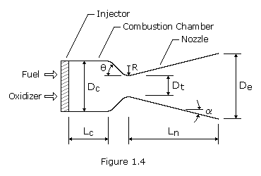
The configuration of a typical conical nozzle is shown in Figure 1.4. The nozzle throat section has the contour of a circular arc with radius R, ranging from 0.25 to 0.75 times the throat diameter, Dt. The half-angle of the nozzle convergent cone section, ![]() , can range from 20 to 45 degrees. The divergent cone half-angle,
, can range from 20 to 45 degrees. The divergent cone half-angle, ![]() , varies from approximately 12 to 18 degrees. The conical nozzle with a 15-degree divergent half-angle has become almost a standard because it is a good compromise on the basis of weight, length, and performance.
, varies from approximately 12 to 18 degrees. The conical nozzle with a 15-degree divergent half-angle has become almost a standard because it is a good compromise on the basis of weight, length, and performance.
Since certain performance losses occur in a conical nozzle as a result of the nonaxial component of the exhaust gas velocity, a correction factor, ![]() , is applied in the calculation of the exit-gas momentum. This factor (thrust efficiency) is the ratio between the exit-gas momentum of the conical nozzle and that of an ideal nozzle with uniform, parallel, axial gas-flow. The value of
, is applied in the calculation of the exit-gas momentum. This factor (thrust efficiency) is the ratio between the exit-gas momentum of the conical nozzle and that of an ideal nozzle with uniform, parallel, axial gas-flow. The value of ![]() can be expressed by the following equation:
can be expressed by the following equation:
![]()
 Bell nozzle: To gain higher performance and shorter length, engineers developed the bell-shaped nozzle. It employs a fast-expansion (radial-flow) section in the initial divergent region, which leads to a uniform, axially directed flow at the nozzle exit. The wall contour is changed gradually enough to prevent oblique shocks.
An equivalent 15-degree half-angle conical nozzle is commonly used as a standard to specify bell nozzles. For instance, the length of an 80% bell nozzle (distance between throat and exit plane) is 80% of that of a 15-degree half-angle conical nozzle having the same throat area, radius below the throat, and area expansion ratio. Bell nozzle lengths beyond approximately 80% do not significantly contribute to performance, especially when weight penalties are considered. However, bell nozzle lengths up to 100% can be optimum for applications stressing very high performance.
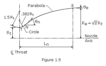
One convenient way of designing a near optimum thrust bell nozzle contour uses the parabolic approximation procedures suggested by G.V.R. Rao. The design configuration of a parabolic approximation bell nozzle is shown in Figure 1.5. The nozzle contour immediately upstream of the throat T is a circular arc with a radius of1.5 Rt. The divergent section nozzle contour is made up of a circular entrance section with a radius of 0.382 Rt from the throat T to the point N and parabola from there to the exit E.
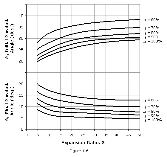
Design of a specific nozzle requires the following data: throat diameter Dt, axial length of the nozzle from throat to exit plane Ln (or the desired fractional length, Lf, based on a 15-degree conical nozzle), expansion ratio ![]() , initial wall angle of the parabola
, initial wall angle of the parabola ![]() n, and nozzle exit wall angle
n, and nozzle exit wall angle ![]() e. The wall angles
e. The wall angles ![]() n and
n and ![]() e are shown in Figure 1.6 as a function of the expansion ratio. Optimum nozzle contours can be approximated very accurately by selecting the proper inputs. Although no allowance is made for different propellant combinations, experience has shown only small effect of the specific heat ratio upon the contour.
e are shown in Figure 1.6 as a function of the expansion ratio. Optimum nozzle contours can be approximated very accurately by selecting the proper inputs. Although no allowance is made for different propellant combinations, experience has shown only small effect of the specific heat ratio upon the contour.
The combustion chamber serves as an envelope to retain the propellants for a sufficient period to ensure complete mixing and combustion. The required stay time, or combustion residence time, is a function of many parameters. The theoretically required combustion chamber volume is a function of the mass flow rate of the propellants, the average density of the combustion products, and the stay time needed for efficient combustion. This relationship can be expressed by the following equation:
![]()
where Vc is the chamber volume, q is the propellant mass flow rate, V is the average specific volume, and ts is the propellant stay-time.
A useful parameter relative to chamber volume and residence time is the characteristic length, L* (pronounced “L star”), the chamber volume divided by the nozzle sonic throat area:
![]()
The L* concept is much easier to visualize than the more elusive “combustion residence time”, expressed in small fractions of a second. Since the value of At is in nearly direct proportion to the product of q and V, L* is essentially a function of ts.
The customary method of establishing the L* of a new thrust chamber design largely relies on past experience with similar propellants and engine size. Under a given set of operating conditions, such as type of propellant, mixture ratio, chamber pressure, injector design, and chamber geometry, the value of the minimum required L* can only be evaluated by actual firings of experimental thrust chambers. Typical L* values for various propellants are shown in the table below. With throat area and minimum required L* established, the chamber volume can be calculated by equation (1.33).
| Propellant Combination | L*, cm |
|---|---|
| Nitric acid/hydrazine-base fuel | 76-89 |
| Nitrogen tetroxide/hydrazine-base fuel | 76-89 |
| Hydrogen peroxide/RP-1 (including catalyst bed) | 152-178 |
| Liquid oxygen/RP-1 | 102-127 |
| Liquid oxygen/ammonia | 76-102 |
| Liquid oxygen/liquid hydrogen (GH2 injection) | 56-71 |
| Liquid oxygen/liquid hydrogen (LH2 injection) | 76-102 |
| Liquid fluorine/liquid hydrogen (GH2 injection) | 56-66 |
| Liquid fluorine/liquid hydrogen (LH2 injection) | 64-76 |
| Liquid fluorine/hydrazine | 61-71 |
| Chlorine trifluoride/hydrazine-base fuel | 51-89 |
Table 1: Chamber Characteristic Length, L*
Three geometrical shapes have been used in combustion chamber design – spherical, near-spherical, and cylindrical – with the cylindrical chamber being employed most frequently in the United States. Compared to a cylindrical chamber of the same volume, a spherical or near-spherical chamber offers the advantage of less cooling surface and weight; however, the spherical chamber is more difficult to manufacture and has provided poorer performance in other respects.
The total combustion process, from injection of the reactants until completion of the chemical reactions and conversion of the products into hot gases, requires finite amounts of time and volume, as expressed by the characteristic length L*. The value of this factor is significantly greater than the linear length between injector face and throat plane. The contraction ratio is defined as the major cross-sectional area of the combuster divided by the throat area. Typically, large engines are constructed with a low contraction ratio and a comparatively long length; and smaller chambers employ a large contraction ratio with a shorter length, while still providing sufficient L* for adequate vaporization and combustion dwell-time.
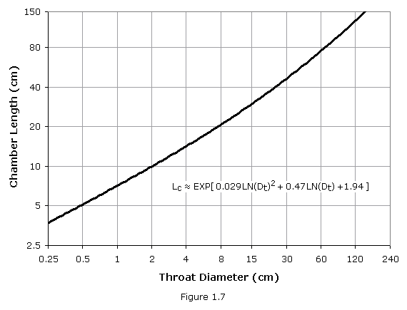
As a good place to start, the process of sizing a new combustion chamber examines the dimensions of previously successful designs in the same size class and plotting such data in a rational manner. The throat size of a new engine can be generated with a fair degree of confidence, so it makes sense to plot the data from historical sources in relation to throat diameter. Figure 1.7 plots chamber length as a function of throat diameter (with approximating equation). It is important that the output of any modeling program not be slavishly applied, but be considered a logical starting point for specific engine sizing.
![]()
Rearranging equation (1.34) we get the following, which can be solved for the chamber diameter via iteration:
![]()
Injector
The injector, as the name implies, injects the propellants into the combustion chamber in the right proportions and the right conditions to yield an efficient, stable combustion process. Placed at the forward, or upper, end of the combustor, the injector also performs the structural task of closing off the top of the combustion chamber against the high pressure and temperature it contains. The injector has been compared to the carburetor of an automobile engine, since it provides the fuel and oxidizer at the proper rates and in the correct proportions, this may be an appropriate comparison. However, the injector, located directly over the high-pressure combustion, performs many other functions related to the combustion and cooling processes and is much more important to the function of the rocket engine than the carburetor is for an automobile engine.
No other component of a rocket engine has as great an impact upon engine performance as the injector. In various and different applications, well-designed injectors may have a fairly wide spread in combustion efficiency, and it is not uncommon for an injector with C* efficiency as low as 92% to be considered acceptable. Small engines designed for special purposes, such as attitude control, may be optimized for response and light weight at the expense of combustion efficiency, and may be deemed very satisfactory even if efficiency falls below 90%. In general, however, recently well-designed injection systems have demonstrated C* efficiencies so close to 100% of theoretical that the ability to measure this parameter is the limiting factor in its determination. High levels of combustion efficiency derive from uniform distribution of the desired mixture ratio and fine atomization of the liquid propellants. Local mixing within the injection-element spray pattern must take place at virtually a microscopic level to ensure combustion efficiencies approaching 100%.
Combustion stability is also a very important requirement for a satisfactory injector design. Under certain conditions, shock and detonation waves are generated by local disturbances in the chamber, possibly caused by fluctuations in mixing or propellant flow. These may trigger pressure oscillations that are amplified and maintained by the combustion processes. Such high-amplitude waves – referred to as combustion instability – produce high levels of vibration and heat flux that can be very destructive. A major portion of the design and development effort therefore concerns stable combustion. High performance can become secondary if the injector is easily triggered into destructive instability, and many of the injector parameters that provide high performance appear to reduce the stability margin.
PROBLEM 1.7

A rocket engine uses the same propellant, mixture ratio, and combustion chamber
pressure as that in problem 1.5.  If the propellant flow rate is 500 kg/s,
calculate the area of the exhaust nozzle throat.

SOLUTION,

   Given:  Pc = 50 × 0.101325 = 5.066 MPa
           Tc = 3,470<sup.o< sup=""> K
           M = 21.40
           k = 1.221
           q = 500 kg/s

   Equation (1.27),

      Pt = Pc × [1 + (k - 1) / 2]-k/(k-1)
      Pt = 5.066 × [1 + (1.221 - 1) / 2]-1.221/(1.221-1)
      Pt = 2.839 MPa = 2.839×10⁶ N/m2

   Equation (1.28),

      Tt = Tc / (1 + (k - 1) / 2)
      Tt = 3,470 / (1 + (1.221 - 1) / 2)
      Tt = 3,125 K

   Equation (1.26),

      At = (q / Pt) × SQRT[ (R' × Tt) / (M × k) ]
      At = (500 / 2.839×10⁶) × SQRT[ (8,314.51 × 3,125) / (21.40 × 1.221) ]
      At = 0.1756 m2
PROBLEM 1.8

The rocket engine in problem 1.7 is optimized to operate at an elevation of 2000
meters.  Calculate the area of the nozzle exit and the section ratio.

SOLUTION,

   Given:  Pc = 5.066 MPa
           At = 0.1756 m2
           k = 1.221

   From Atmosphere Properties,

      Pa = 0.0795 MPa

   Equation (1.29),

      Nm2 = (2 / (k - 1)) × [(Pc / Pa)(k-1)/k - 1]
      Nm2 = (2 / (1.221 - 1)) × [(5.066 / 0.0795)(1.221-1)/1.221 - 1]
      Nm2 = 10.15
      Nm = (10.15)1/2 = 3.185

   Equation (1.30),

      Ae = (At / Nm) × [(1 + (k - 1) / 2 × Nm2)/((k + 1) / 2)](k+1)/(2(k-1))
      Ae = (0.1756 / 3.185) × [(1 + (1.221 - 1) / 2 × 10.15)/((1.221 + 1) / 2)](1.221+1)/(2(1.221-1))
      Ae = 1.426 m2

   Section Ratio,

      Ae / At = 1.426 / 0.1756 = 8.12
PROBLEM 1.9
For the rocket engine in problem 1.7, calculate the volume and dimensions of a
possible combustion chamber. The convergent cone half-angle is 20 degrees.
SOLUTION,
Given: At = 0.1756 m2 = 1,756 cm2
Dt = 2 × (1,756/ )1/2 = 47.3 cm
 = 20o
From Table 1,
L* = 102-127 cm for LOX/RP-1, let's use 110 cm
Equation (1.33),
Vc = At × L*
Vc = 1,756 × 110 = 193,160 cm3
From Figure 1.7,
Lc = 66 cm (second-order approximation)
Equation (1.35),
Dc = SQRT[(Dt3 + 24/ × tan × Vc) / (Dc + 6 × tan × Lc)]
Dc = SQRT[(47.33 + 24/ × tan(20) × 193,160) / (Dc + 6 × tan(20) × 66)]
Dc = 56.6 cm (four interations)
= 20o
From Table 1,
L* = 102-127 cm for LOX/RP-1, let's use 110 cm
Equation (1.33),
Vc = At × L*
Vc = 1,756 × 110 = 193,160 cm3
From Figure 1.7,
Lc = 66 cm (second-order approximation)
Equation (1.35),
Dc = SQRT[(Dt3 + 24/ × tan × Vc) / (Dc + 6 × tan × Lc)]
Dc = SQRT[(47.33 + 24/ × tan(20) × 193,160) / (Dc + 6 × tan(20) × 66)]
Dc = 56.6 cm (four interations)