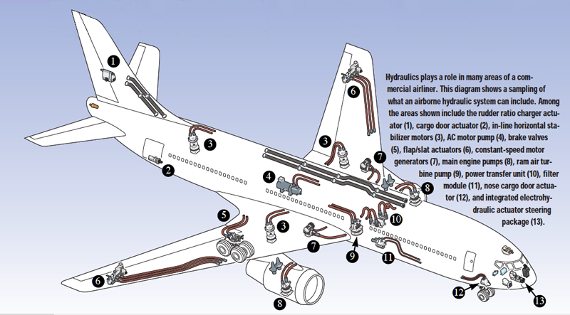
Aircraft hydraulic systems can be a challenge to design engineers, due to many constraints that are not encountered when designing a system for in-plant or mobile applications. Hydraulic technology first gained a foothold in aircraft flight control during World War II, when hydraulics was introduced for some secondary systems’ control. However, as aircraft flight performance and capabilities increased, hydraulics began to play a larger role in the critical operation and safety of airliners, helicopters, and high-performance military aircraft. Functions often powered by hydraulics in commercial aircraft include primary flight controls, flap/slat drives, landing gear, nose wheel steering, thrust reversers, spoilers, rudders, cargo doors, and emergency hydraulic-driven electrical generators.
In modern aircraft, some of the places that hydraulics come into play include primary flight controls, flap/slat drives, landing gear, nose wheel steering, thrust reversers, spoilers, rudders, cargo doors, and emergency hydraulic-driven electrical generators. Military aircraft also use hydraulics on gun drives, weapons-bay doors, and hydraulic-motor-driven-fan heat exchangers. Factors that must be addressed on an aircraft include pressure conditions (both internal and ambient), temperature extremes, weight, speed, materials, reliability, fluid compatibility, leaks, cost, noise, and redundancy.
Pressure and temperature
Pressures on aircraft hydraulic systems run higher than on many industrial applications, which generally remain in the 1,500 to 2,000 psi range. Most commercial airliners run at 3,000 psi, with military planes using 4,000 psi systems (although some new military aircraft have made the move to 5,000 psi). The impetus for higher pressures comes from space considerations and the need for light weight, because actuators can generate higher torque forces and power from a smaller envelope.
Not only must the systems deal with the expected variables in ambient temperature that are experienced across the whole of the planet’s surface, but temperatures fall well below zero at an aircraft’s cruising altitude. Most commercial systems are designed to tolerate conditions from –65° to 160° F, while military aircraft can handle a temperature range of –65° to 275° F.
Fluids for high and low temperatures
Fluids used on aircraft have a relatively flat (compared to industrial fluids) viscosity vs. temperature curve — in other words, they are somewhat thin. Additionally, these fluids must be fire resistant, a critical concern when the nearest fire department may be only five miles away — but five miles straight down. One characteristic of aircraft hydraulic fluids that makes them unique is that they remain fluid at –65° F, a temperature at which water- and vegetable-based oils will freeze. The current fluids of choice in the aerospace industry are:
MIL-H-5606 — first introduced over fifty years ago and still used on many aircraft. Used on business jets and many U.S. Air Force aircraft, it is highly flammable and considered responsible for the loss of at least one military aircraft, due to the fire created.
MIL-H-83282 — first used by the Air Force in 1982 and the U.S. Navy in 1997, it is less flammable than 5606, but much more viscous at low temperature. The lower temperature limit of MIL-H-83282 is considered –40° F, and it is used in virtually all Navy aircraft.
MIL-H-87257 — this newest fluid is used in C135, E3, and U2 aircraft; it is less flammable than 5606 (similar to 83282) but its viscosity at low temperatures allows use down to –65° F. Considered the fluid of choice for newer aircraft being developed, and
Skydrol and Hyjet — these alkyl phosphate ester based fluids are used on commercial aircraft, and are less flammable than the military fluids described above. Maximum temperature limit is 160° F. These fluids have been around at least since the 1960s.
Component and system reliability
Great emphasis is placed on maintenance schedules, filtration, and general maintenance of fluid conditions on aircraft. Ed Bush, of Vickers Industrial & Mobile Group, Rochester Hills, Mich., explains, “In industrial applications, the PLC is operating the system, so you design it accordingly. On mobile equipment, who knows who operates it? You hope people who know what they’re doing. On aircraft, the reliability is so critical, you have to throw everything in — redundant systems, very specific maintenance schedules, and stringent guidelines on the components themselves.”
Parts manufactured for use on aircraft do face much tougher guidelines on design, construction, and quality control than those used in most industrial applications. A typical hydraulic pump used on an aircraft may cost between $4,000 and $25,000, compared with a comparable industrial pump’s cost of $400 or less.
Why these extra costs? Consider the following differences on a pump:
- Great attention must be paid to shoe bearing plates and plate faces, due to poor fluid qualities.
- The pump must be compatible with these poor-quality fluids.
- Aluminum is often used, due to weight considerations.
- It must be smaller and have a higher operating speed.
- It must be built to withstand severe vibration, shock and g-forces. (Helicopter applications see more extreme vibration and shock forces than a shop floor does.)
Even the packaging of many components is more exotic than with the average industrial component. Phil Galloway, engineering manager, military programs, Vickers Aerospace Marine Defense Fluid Power Div., Jackson, Miss., offers, “Since minimum weight is the single most important objective, it is unlikely that the exact valve is available. Thus, it will most likely need to be modified. Each added valve is usually custom designed to suit its function. Since aircraft quantities are relatively small, modular, low-cost, mass-produced valves are not generally used.”
Bootstrap (pressurized) reservoirs are used on military aircraft to keep the charge inlet of pumps pressurized to prevent cavitation. Imagine the problems that could result if a military fighter used a traditional industrial reservoir and executed a roll. Commercial airliners often use reservoirs with an air charge. Space and weight limitations in aircraft demand that reservoirs be much smaller than they are in conventional hydraulic systems. Reservoir size is optimized for aircraft so that only the amount of fluid needed for proper function is carried. Sizing considerations often include:
- differential volume requirements due to actuator differential areas,
- volume required to fill accumulators when totally discharged,
- volume required to make up fluid when total thermal contraction and expansion of fluid is experienced, and
- amount needed to minimize the frequency of filling.
There is currently a focus on building quality systems on a system level. As part of this movement, aircraft companies are increasingly looking to component manufacturers to provide complete aircraft hydraulic systems, instead of a myriad of unconnected parts.
The majority of aircraft have three or four redundant hydraulic systems, which are geographically separate in many cases (especially on fighting aircraft, which must be able to survive being hit by enemy fire).
Particularly interesting is the RAT, or Ram Air Turbine. This last-gasp system comes online in an extreme emergency. The RAT is a spring-loaded device usually located near the nose of the plane, which is deployed in case of a total loss of power. The RAT basically consists of a propeller that turns a hydraulic pump – providing enough power to allow the pilot to make rudimentary landing gear and aileron adjustments upon landing. Its only drawback is noise – commonly on the scale of 120 dBA.
Other factors
When people talk about noise control, they usually aren’t referring to airline hydraulic systems. After all, why bother tweaking a system to achieve a noise level several decibels lower, when the plane’s engines themselves are drowning out any noise that the hydraulics could possibly make? However, aircraft engines have been engineered to run quieter in recent years both in takeoff and landing situations to appease communities in close proximity to airports. Quieter operation is also important during midflight for passenger comfort. Thus, noise has become an important issue in aricraft design.
1 – Basic Hydraulic Systems
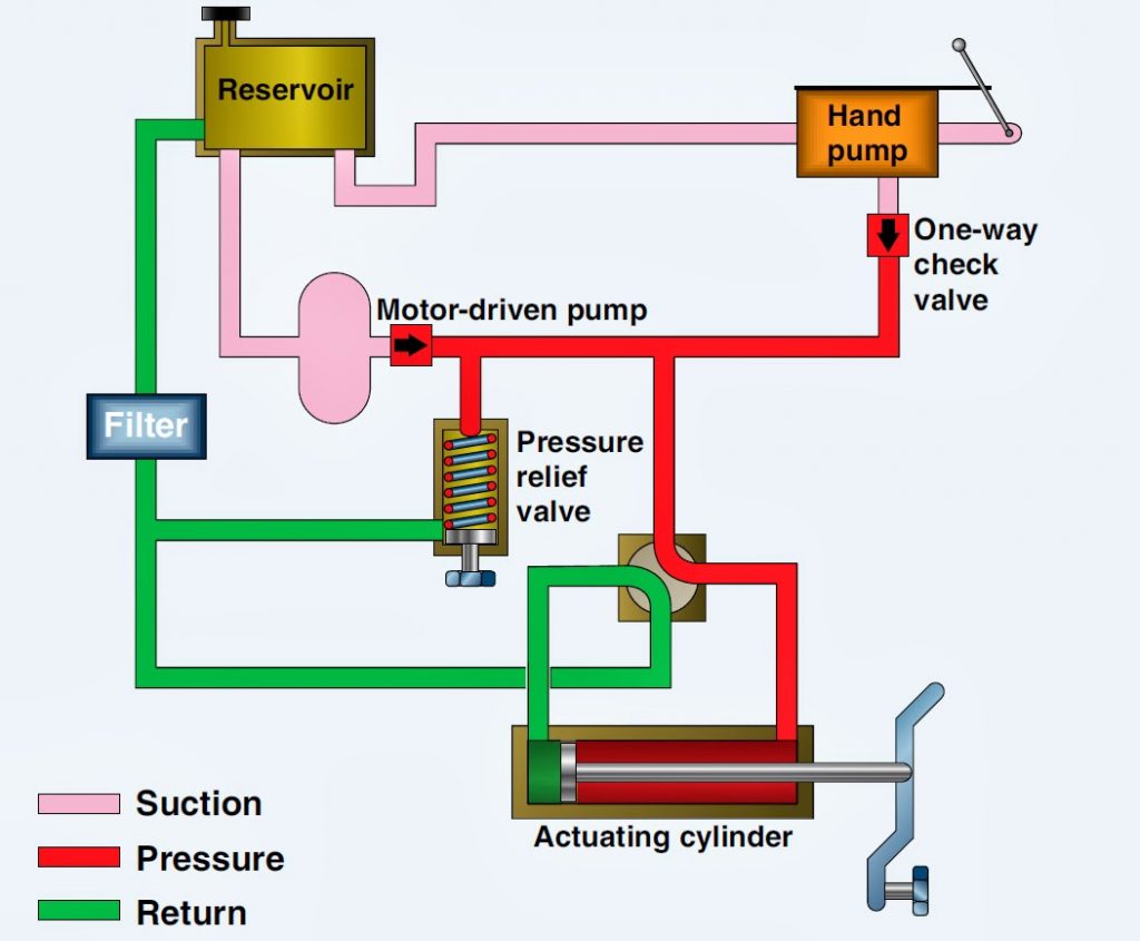
Regardless of its function and design, every hydraulic system has a minimum number of basic components in addition to a means through which the fluid is transmitted. A basic system consists of a pump, reservoir, directional valve, check valve, pressure relieve valve, selector valve, actuator, and filter.
1.1 Open Center Hydraulic Systems
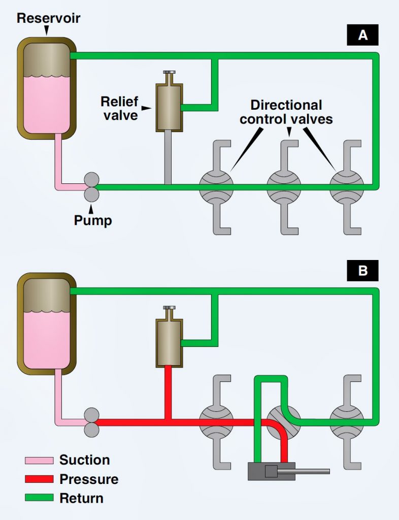
An open center system is one having fluid flow, but no pressure in the system when the actuating mechanisms are idle. The pump circulates the fluid from the reservoir, through the selector valves, and back to the reservoir. The open center system may employ any number of subsystems, with a selector valve for each subsystem. Unlike the closed center system, the selector valves of the open center system are always connected in series with each other. In this arrangement, the system pressure line goes through each selector valve. Fluid is always allowed free passage through each selector valve and back to the reservoir until one of the selector valves is positioned to operate a mechanism.
When one of the selector valves is positioned to operate an actuating device, fluid is directed from the pump through one of the working lines to the actuator. With the selector valve in this position, the flow of fluid through the valve to the reservoir is blocked. The pressure builds up in the system to overcome the resistance and moves the piston of the actuating cylinder; fluid from the opposite end of the actuator returns to the selector valve and flows back to the reservoir. Operation of the system following actuation of the component depends on the type of selector valve being used. Several types of selector valves are used in conjunction with the open center system. One type is both manually engaged and manually disengaged. First, the valve is manually moved to an operating position. Then, the actuating mechanism reaches the end of its operating cycle, and the pump output continues until the system relief valve relieves the pressure. The relief valve unseats and allows the fluid to flow back to the reservoir. The system pressure remains at the relief valve set pressure until the selector valve is manually returned to the neutral position. This action reopens the open center flow and allows the system pressure to drop to line resistance pressure.
The manually engaged and pressure disengaged type of selector valve is similar to the valve previously discussed. When the actuating mechanism reaches the end of its cycle, the pressure continues to rise to a predetermined pressure. The valve automatically returns to the neutral position and to open center flow.
1.2 Closed-Center Hydraulic Systems
In the closed-center system, the fluid is under pressure whenever the power pump is operating. The three actuators are arranged in parallel and actuating units B and C are operating at the same time, while actuating unit A is not operating. This system differs from the open-center system in that the selector or directional control valves are arranged in parallel and not in series. The means of controlling pump pressure varies in the closed-center system. If a constant delivery pump is used, the system pressure is regulated by a pressure regulator. A relief valve acts as a backup safety device in case the regulator fails.
If a variable displacement pump is used, system pressure is controlled by the pump’s integral pressure mechanism compensator. The compensator automatically varies the volume output. When pressure approaches normal system pressure, the compensator begins to reduce the flow output of the pump. The pump is fully compensated (near zero flow) when normal system pressure is attained. When the pump is in this fully compensated condition, its internal bypass mechanism provides fluid circulation through the pump for cooling and lubrication. A relief valve is installed in the system as a safety backup. An advantage of the open-center system over the closed-center system is that the continuous pressurization of the system is eliminated. Since the pressure is built up gradually after the selector valve is moved to an operating position, there is very little shock from pressure surges. This action provides a smoother operation of the actuating mechanisms. The operation is slower than the closed-center system, in which the pressure is available the moment the selector valve is positioned. Since most aircraft applications require instantaneous operation, closed-center systems are the most widely used.
2 Boeing 737 Next Generation Hydraulic System
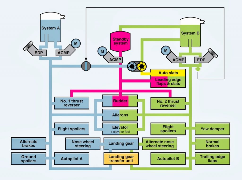
The Boeing 737 Next Generation has three 3,000 psi hydraulic systems: system A, system B, and standby. The standby system is used if system A and/or B pressure is lost. The hydraulic systems power the following aircraft systems:
- – Flight controls
- – Leading edge flaps and slats
- – Trailing edge flaps
- – Landing gear
- – Wheel brakes
- – Nose wheel steering
- – Thrust reversers
- – Autopilots
2.2 Hydraulic Reservoirs
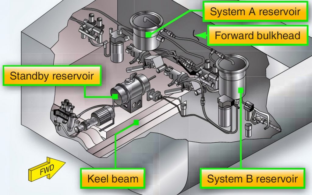
The system A, B, and standby reservoirs are located in the wheel well area. The reservoirs are pressurized by bleed air through a pressurization module. The standby reservoir is connected to the system B reservoir for pressurization and servicing. The positive pressure in the reservoir ensures a positive flow of fluid to the pumps. The reservoirs have a standpipe that prevents the loss of all hydraulic fluid if a leak develops in the engine-driven pump or its related lines. The engine-driven pump draws fluid through a standpipe in the reservoir and the AC motor pump draws fluid from the bottom of the reservoir.
2.3 Hydraulic Pumps
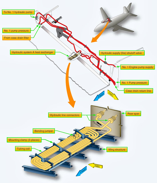
Both A and B hydraulic systems have an engine-driven pump (EDP) and an ACMP. The system A engine-driven pump is installed on the number 1 engine and the system B engine-driven pump is installed on the number 2 engine. The AC pumps are controlled by a switch on the flight deck. The hydraulic case drain fluid that lubricates and cools the pumps return to the reservoir through a heat exchanger. The heat exchanger for the A system is installed in the main fuel tank No. 1, and the heat exchanger for the B system is installed in the main fuel tank No. 2. Minimum fuel for ground operation of electric motor-driven pumps is 1,675 pounds in the related main tank. Pressure switches, located in the EDP and ACMP pump output lines, send signals to illuminate the related LOW PRESSURE light if pump output pressure is low. The related system pressure transmitter sends the combined pressure of the EDP and ACMP to the related hydraulic system pressure indicator.
2.4 Filter Units
Filter modules are installed in the pressure, case drain, and return lines to clean the hydraulic fluid. Filters have a differential pressure indicator that pops out when the filter is dirty and needs to be replaced.
2.5 Power Transfer Unit (PTU)
The purpose of the PTU is to supply the additional volume of hydraulic fluid needed to operate the autoslats and leading edge flaps and slats at the normal rate when system B EDP malfunctions. The PTU unit consists of a hydraulic motor and hydraulic pump that are connected through a shaft. The PTU uses system A pressure to drive a hydraulic motor. The hydraulic motor of the PTU unit is connected through a shaft with a hydraulic pump that can draw fluid from the system B reservoir. The PTU can only transfer power and cannot transfer fluid. The PTU operates automatically when all of the following conditions are met:
- – System B EDP pressure drops below limits.
- – Aircraft airborne.
- – Flaps are less than 15° but not up.
2.6 Landing Gear Transfer Unit
The purpose of the landing gear transfer unit is to supply the volume of hydraulic fluid needed to raise the landing gear at the normal rate when system A EDP is lost. The system B EDP supplies the volume of hydraulic fluid needed to operate the landing gear transfer unit when all of the following conditions are met:
- – Aircraft airborne.
- – 1 engine rpm drops below a limit value.
- – Landing gear lever is up.
- – Either or both main landing gear not up and locked.
2.7 Standby Hydraulic System
The standby hydraulic system is provided as a backup if system A and/or B pressure is lost. The standby system can be activated manually or automatically and uses a single electric ACMP to power:
- – Thrust reversers
- – Rudder
- – Leading edge flaps and slats (extend only)
- – Standby yaw damper
2.8 Indications
A master caution light illuminates if an overheat or low pressure is detected in the hydraulic system. An overheat light on the flight deck illuminates if an overheat is detected in either system A or B and a low-pressure light illuminates if a low pressure is detected in system A and B.


