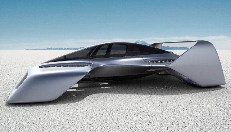
LX-1 flying car revealed – ‘hyper eVTOL’ prototype
The aircraft is a personal automobile for the sky for its creators.
Below the audio version of this article:
The dream of flying cars is ancient, and yet, we have yet to see this dream become a reality.
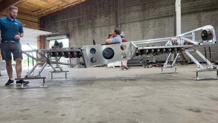
But a manned alpha prototype of an eVTOL (electric vertical take-off and landing) aircraft has been revealed, bringing us closer to that dream.
While the experimental prototype LX-1 doesn’t display the dashing looks from earlier renders, its aluminum frame was designed to test the propulsion system, consisting of four banks of at least 72 small vertical-lift fans. And it has two larger diameter fans at the rear, giving it some horizontal thrust, according to New Atlas.
LEO Flight previously announced its LEO Coupe, which is designed by award-winning designer Carlos Salaff of SALAFF Automotive, and features a revolutionary, proven electric propulsion system created by Pete Bitar of Electric Jet Aircraft, a DARPA-funded propulsion system. The aircraft is called a personal automobile for the sky by its creators.
The aircraft will have up to a zooming speed of 250 mph (400 kph) and be able to travel 300 miles (483 km) on a single charge.
The final version of the aircraft will run no less than 200 small vertical jets, each being 4.4 inches (11 cm) in diameter and producing 11.7 lb (5.3 kg) of thrust for a total of over 2,300 lb (1,043 kg) of thrust, Bitar now told New Atlas.
The aircraft will have an empty weight of 1,100 lb (499 kg) and be able to carry a 510 lb (231 kg) payload.
The aircraft will be rather compact, with a size of 10′ x 20′ (3m x 6m). LEO Coupes’ size enables it to be privately owned, used as an air taxi, and as a vehicle that can be landed anywhere where space is limited.
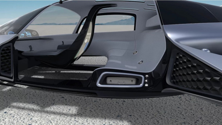
The aircraft will have gull-wing doors leading into a cabin for three adults, including the pilot. According to LEO Flight, the aircraft will have easy-to-learn semi-autonomous controls that make flight simple.
The vehicle’s wings will be non-exposed rotors to eliminate danger to those around the aircraft.
LEO plans to sell the Coupe as a personal eVTOL aircraft, promising a somewhat optimistic range of around 300 miles (480 km) out of just 66 kWh of battery, with a price tag of $459,900.
VertiStop for mobile charging
LEO Flight also announced its rapid-charging solution for the LEO Coupe, VertiStop. While LEO Coupe can be recharged at home and landed on just about any surface, travelers can also use VertiStop as a compact charging and landing pad.
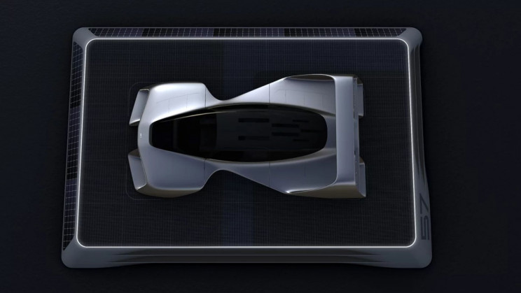
VertiStop can be rapidly deployed on rooftops and parking structures. Supporting LEO Flight’s pathway to building an extensive network of charging and parking spots.
The VertiStop unit provides a power grid connection and fast charging for the vehicle. Its integral solar arrays supplement energy needs, while its mesh top will help absorb air currents from LEO’s jet system.
It also looks ideal for fire rescue, medevac, Coast Guard, tourism, exploration, and most terrain without developed road infrastructure.
This novel aircraft is an all-in-one vehicle with its abilities, looks, and its probable forms of utilization.
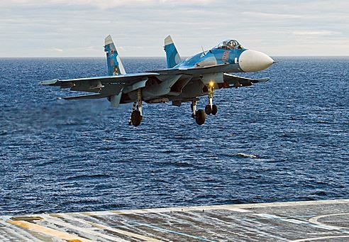
How do planes take off and land on aircraft carriers?
A plane needs hundreds of meters to take off and land safely. What are the technologies that allow planes to do this in the space of an aircraft carrier?

In the new Top Gun we will see Tom Cruise, or rather Captain Pete “Maverick” Mitchell, take off from an American super carrier, aboard a Boeing F / A-18 Super Hornet. But how does a nearly 3000 kg plane take off in few tens of meters of an aircraft carrier? The secret is contained in a mechanism called “catapult” for take-off and with a system of cables for fitting.
The difference between take-off and landing on aircraft carriers
The first thing to do is to clarify the difference between taking off and landing on an aircraft carrier. They must be distinguished not only because they are two different flight phases (obviously), but also because they are based on two different mechanisms.
Taking the CATOBAR aircraft carriers for example, take-off is performed in the front part of the ship with the aid of the so-called catapult, while the landing begins in the bow part with the aid of cables. Let’s see the two phases in detail.

How does the take-off work?
Takeoff, by definition, is the maneuver by which an aircraft leaves the ground, in this case from the deck of an aircraft carrier. On normal asphalt runways, without the aid of external mechanisms and relying only on the engines, even with the afterburners activated, the normal take-off space is of the order of hundreds of meters. The take-off run depends on the type of aircraft and its configuration. On aircraft carriers, the steam catapult is used to launch an aircraft up to take-off speed.
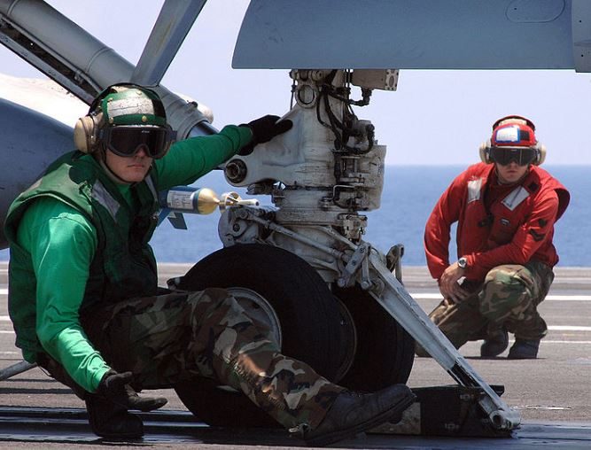
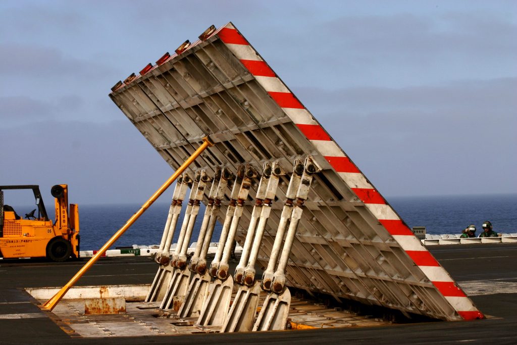
The launch system consists of a groove made on the flight deck, inside which there is an aircraft coupling system capable of accelerating the aircraft until it reaches high speeds. The nose gear of the aircraft is connected to the device in the furrow and the entire aircraft is launched at a speed sufficient for take-off from the ship. Behind the aircraft a panel rises to protect the deck from the exhaust of the powerful engines.
To create the “catapult” effect, a steel bar is used which remains attached to the nose gear of the plane to be launched. Upon take-off, latches are released – which in turn release a piston inserted into a pressure circuit where steam had been accumulated. The piston moves and the aircraft reaches a speed sufficient for takeoff in 4 seconds.
The development of the first steam catapults dates back to the early 1930s, when the first reconnaissance planes were launched from the deck, such as seaplanes. At the time, there were no recovery systems for the aircraft, which were hoisted from the sea after their landing.
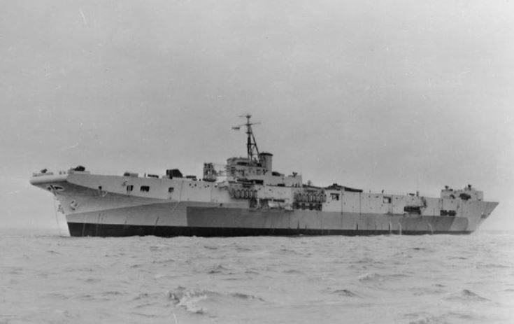
With the development of the aircraft and with the consequent increase in the weight of the aircraft, a more performing system was necessary to be able to launch the aircraft. Starting from 1950, the first steam catapults of modern conception began to be used, similar to those used to this day on major aircraft carriers. The first military ship to be equipped with a steam catapult of this type was the English HMS Perseus.
How does the landing work?
Landing on the aircraft carrier is an extremely difficult and dangerous maneuver. For this particular phase of flight, pilots perform numerous exercises in any light condition. It is also extremely stressful, both for the pilots and for the structure of the aircraft itself: it goes from over 200 km / h to 0 km / h in just a few tens of meters, with a very strong deceleration – and it is precisely for this reason the pilots they must be well trained.
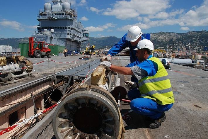
The system used today in most aircraft carriers is the stop cable which is hooked by the tail hook of the aircraft during the docking phase. The operation is very simple: the pilot in the approach phase releases the hook (present on board the aircraft). Up to three equidistant cables are stretched across the deck at a certain distance from the stern. To stop the aircraft, the pilot must therefore “grab” one of the three cables and, if they are missing, it would be necessary to repeat the maneuver.
At the moment of coupling, the energy of the plane’s motion is transferred to the cable, which through pulleys (usually lateral) sends it back to the stopping motor, dissipating it. When the docking bracket and cable are pulled by the aircraft, the shutdown motor is activated ensuring a “soft” landing for the aircraft. At the end of this maneuver the pilot detaches the tail hook from the bracket and the cable returns to the extended position.
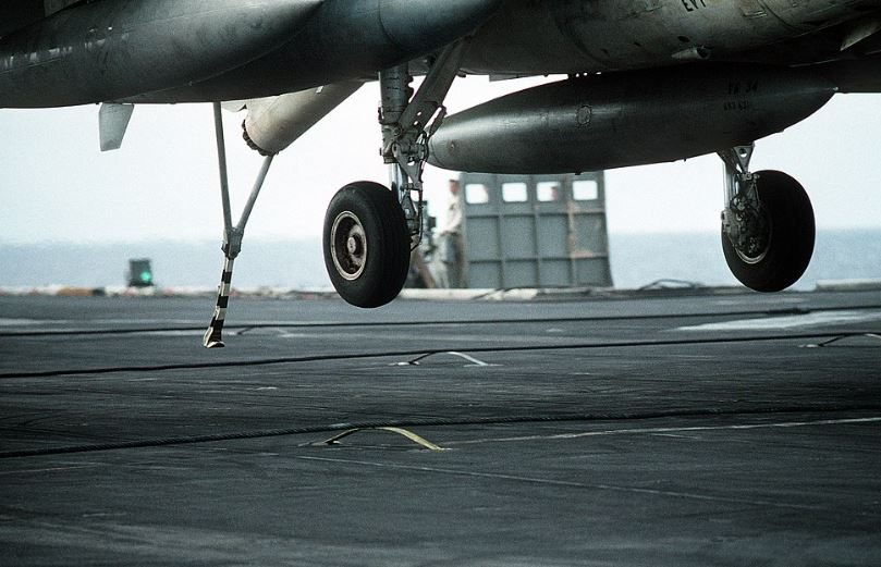
An aircraft landing on an aircraft carrier holds the engine at approximately 85% of maximum power. If the cable stops the plane, the pilot turns off the engine and releases the cable, otherwise he makes a go-around, having enough power to continue the ride on the bridge he can regain altitude, make a new turn and repeat the landing. The modern aircraft carriers of the U.S. Navy use Mark 7 Mod 3 cables which have the ability to stop a 22,000kg aircraft at speeds of 240km / h in a space of 104m.
The “cable + hook” technique was used as early as 1911, but it was only with the development of increasingly heavier and more performing aircraft that this technology began to be used: after the Second World War this system was adopted by most aircraft carriers, in place of the previously existing barriers or barricades.
Ah, quoting Top Gun once again, let’s remember that for an F-14 Tomcat the take-off run is 465m, while to land it needs 785m of runway. On an aircraft carrier, it performs these maneuvers within a few tens of meters.
New kind of solar cells generate electricity even at night
Play below for the audible version of this article:
UNSW scientists have announced a breakthrough in the field of renewable energy. They have developed a new kind of solar cells that can produce electricity even at night.’
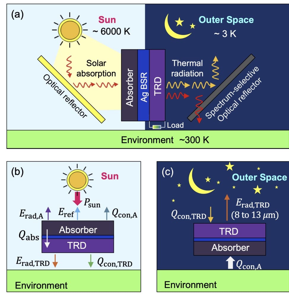
Known as ‘Night-time’ solar power, the technology generates electricity from heat radiated as infrared light, in the same way as the Earth cools by radiating into space at night. However, it generates a very small amount of energy, but scientists hope to improve the results in the future.
A semiconductor device called a thermoradiative diode, composed of materials found in night-vision goggles was used to generate power from infrared light emission. This is an unambiguous demonstration of electrical power from a thermoradiative diode.
Like the solar cell generates electricity by absorbing sunlight, the thermoradiative diode generates electricity by emitting infrared light into a colder environment. In both cases, the temperature difference is what lets us generate electricity.
This ‘Night-time’ solar power technology is an exciting confirmation of a previously theoretical process. It is the first step toward making specialized and much more efficient devices that could one-day capture energy at a much larger scale.
Dr. Michael Nielsen, co-author of the paper, said: “Even if the commercialization of these technologies is still away down the road, being at the very beginning of an evolving idea is such an exciting place to be as a researcher.”
“By leveraging our knowledge of how to design and optimize solar cells and borrowing materials from the existing mid-infrared photodetector community, we hope for rapid progress towards delivering the dream of solar power at night.”
A/Prof. Ekins-Daukes said, “Down the line, this technology could potentially harvest that energy and remove the need for batteries in certain devices – or help to recharge them. That isn’t something where conventional solar power would necessarily be a viable option.”
Scientists hope that industry leaders will recognize the potential for the new technology and support its further development.
This could have niche applications for spacecraft or satellites or devices that need at least some power around the clock. Any consistent sun light would work better to have regular solar and 150 to 250 watt hours per square meter of batteries to cover night time operation.
A/Prof. Ekins-Daukes said, “Right now, the demonstration we have with the thermoradiative diode is relatively, very low power. One of the challenges was detecting it. But the theory says it is possible for this technology to ultimately produce about 1/10th of the power of a solar cell.”
“I think for this to be a breakthrough technology, we shouldn’t underestimate the need for industries to step in and drive it. There’s still about a decade of university research work to be done here. And then it needs industry to pick it up.”
“If the industry can see this is a valuable technology for them, then progress can be extremely fast.”
High-power microwave technology to use against drone threats
Play below for the audible version of this article:
The Pentagon’s Joint Counter-Small Unmanned Aircraft Systems Office has finished tests of a high-power microwave technology called The Epirus system that has the capacity of disabling several drones at once, according to a report by Defense News published on Wednesday.
Testing the effector’s emissions
This isn’t the Pentagon’s first demonstration of the technology. It conducted two more last year in the spring and fall. This most recent test took place during a whole week from April 4 to 22 at Yuma Proving Ground, Arizona.
“What we primarily focused on in that first week for high-power microwave was how well the effector emitted,” Michael DiGennaro, the test team lead for JCO’s acquisition and resourcing division, said during a May 11 media roundtable.
“We were looking at range to engage the targets that were inbound and the amount of time it took to either deter or defeat the target.” DiGennaro further added that the Epirus system proved successful in its assigned activities, and it “was able to defeat targets in the range that is normally associated with what is currently in the field, and has the promise to be a little bit more effective in the future.”
Countering small UAS
The Pentagon also evaluated technologies that could counter small Unmanned Aircraft Systems (UAS), choosing from a total of 25 submitted whitepapers for the process. The five chosen companies were Anduril Industries, Black Sage, CACI (California Analysis Center, Inc), Rafael Systems Global Sustainment, and SAIC (Science Applications International Corporation).
“We had five very complex architectures out there,” DiGennaro said. “Each of them brought a host of different components for detection, identification, tracking, and defeat, and we tested against each of those components both individually and then as a system, culminating in a ‘defend the forward-operating base’ scenario.” These military exercises resulted in the collection of important data, which will be shared with the Defense Department at a later date.
The First-Ever Image of The Black Hole at The Center of The Milky Way
Play below for the audible version of this article:
Four and a half billion years ago, our pale blue dot was born in the rubble left over from the birth of a star. Since then, we’ve been locked in a cosmic dance; Earth whirls around the Sun; and the Sun whirls around the galactic center – the dark, mysterious heart of the Milky Way.
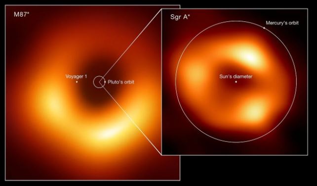
Contained in that dark heart, around which the entire galaxy revolves, is a supermassive black hole named Sagittarius A*, clocking in at roughly 4.3 million times the mass of the Sun. We’ve been able to infer its presence, and measure it, based on the movements of objects around it, but never had we seen the object itself.
That image at the top of the screen – looking like a glorious blurry orange donut – is the dust around and shadow of Sgr A* itself, seen by humanity for the very first time, thanks to the hard work of the Event Horizon Telescope collaboration.
“We were stunned by how well the size of the ring agreed with predictions from Einstein’s Theory of General Relativity,” said EHT Project Scientist Geoffrey Bower of Academia Sinica in Taipei.
“These unprecedented observations have greatly improved our understanding of what happens at the very center of our galaxy, and offer new insights on how these giant black holes interact with their surroundings.”
The achievement comes three years after the collaboration released the first image of a black hole’s shadow ever obtained – a supermassive black hole named M87*, clocking in at 6.5 billion times the mass of the Sun, at the center of a galaxy 55 million light-years away.
Sgr A* is considerably closer to us, at a distance of around 25,800 light-years. But the two black holes presented very different challenges.
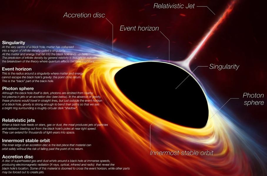
Attempting to image a black hole is attempting to image the invisible. Black holes give off no radiation we can detect. They’re so dense that, past a certain point known as the event horizon, not even light, the fastest thing in the Universe, is able to achieve escape velocity from their gravitational pull.
M87* is what we refer to as an active galactic nucleus. That means it’s feeding – surrounded by an enormous disk of dust and gas that is getting pulled into the black hole. The insane friction and gravity involved heats this material so that it glows brightly. That’s what we see in the picture of M87*, with the shadow of the black hole in the center of the glowing material. Sagittarius A* may be closer… but it’s nowhere near as active. In fact, if Sgr A* were a person, it would only consume the equivalent of a grain of rice every million years.
Moreover, the Milky Way galactic center is thick with dust that obscures much of what is contained therein.
Scientists had previously detected a cloud of gas orbiting Sgr A*, an accretion disk of the black hole’s very own, but it’s relatively cool and glowing much more faintly. Moreover, because the black hole is smaller, the disk’s orbital period is smaller, which means the light changes on very rapid timescales.
“The gas in the vicinity of the black holes moves at the same speed – nearly as fast as light – around both Sgr A* and M87*,” said astronomer Chi-kwan (‘CK’) Chan of the University of Arizona.
“But where gas takes days to weeks to orbit the larger M87*, in the much smaller Sgr A* it completes an orbit in mere minutes. This means the brightness and pattern of the gas around Sgr A* was changing rapidly as the EHT Collaboration was observing it – a bit like trying to take a clear picture of a puppy quickly chasing its tail.” Within, something shines brightly in radio wavelengths – that would be Sgr A*, but we’d never been able to obtain a detailed view of it.
To overcome these challenges, the Event Horizon Telescope combined eight telescopes from around the world, which worked together in what is essentially an Earth-sized telescope, with spectacular resolution.
A large number of images were taken during an observing campaign in 2017, producing six terabytes of data. These data had to be processed and analyzed – a process that took years, and the development of new algorithms to compensate for the rapid changeability.
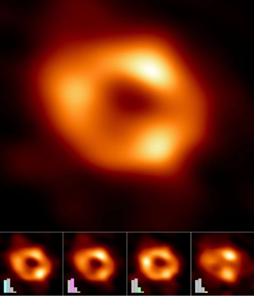
The images were grouped into four classed based on similar features, which you can see at the bottom of the image above. The bar graphs show the relative number of images belonging to each cluster.
Scientists are going to be chewing over the incredible results for some time to come. Supermassive black holes are a cosmic mystery. We don’t know how they manage to get so big – Sgr A* is actually pretty titchy for one of these behemoths – or how they formed in the first place, at the dawn of time. They are, however, major drivers in the evolution of the cosmos. Entire galaxies swirl around them; they control star formation, even outside their own galaxies.
The supermassive black holes that we usually study are active, like M87*. That’s because the material in the space around them emits light, and the magnetic fields of the black holes can accelerate jets into intergalactic space, both of which can tell us about the black hole itself.
Sgr A*’s quiescence may have made it more challenging to image, but that very characteristic makes it extraordinary as an object of study. Because it’s not blazing with light like a more active black hole, we might be able to see the environment around it a little more clearly, which in turn might give us a better window into event horizon physics.
This could help us understand all sorts of black hole mysteries, such as how accretion works, how jets are launched, even whether general relativity has accurately described the extreme space-time in the vicinity of a black hole.
Fascinatingly, the two black holes appear very similar. This, the researchers said, means we can make certain inferences about black holes.
“We have two completely different types of galaxies and two very different black hole masses, but close to the edge of these black holes they look amazingly similar,” said astronomer Sera Markoff of the EHT Science Council the University of Amsterdam in the Netherlands.
“This tells us that General Relativity governs these objects up close, and any differences we see further away must be due to differences in the material that surrounds the black holes.”
The new image opens up a new door for studying these extreme objects. One image of a black hole is amazing. Two means that not only was that first result real, we now have a point of comparison to understand how these incredible, extreme objects operate.
“Now we can study the differences between these two supermassive black holes to gain valuable new clues about how this important process works,” said astrophysicist Keiichi Asada of Academia Sinica.
“We have images for two black holes – one at the large end and one at the small end of supermassive black holes in the Universe – so we can go a lot further in testing how gravity behaves in these extreme environments than ever before.”
The new results have been published in a special issue of The Astrophysical Journal Letters.
SpaceX, Humanity on the Mars before the end of the 2020s
Visitors to the Red Planet will reach it aboard SpaceX’s Starship.
Play below for the audible version of this article:
In December 2021, Elon Musk predicted that humans will be on Mars within a decade. Now, SpaceX President and Chief Operating Officer Gwynne Shotwell told CNBC‘s Shepard Smith on Saturday that humanity will touch the ground on the Red Planet before the end of the 2020s. “I think it will be in this decade, yes. People on the moon, sooner,” Shotwell said.
“I think we need to get a large delivery to the surface of Mars, and then people will start thinking harder about it,” she added. “And then, I think within five or six years, people will see that that will be a real place to go.” How do the ambitious executives plan to make it to Mars? Aboard their new ship: Starship.
Starship is designed to be the first reusable spacecraft that will be able to take crew and cargo to the Moon and Mars before returning to Earth and it is so advanced that it supposedly has got the competition worried.
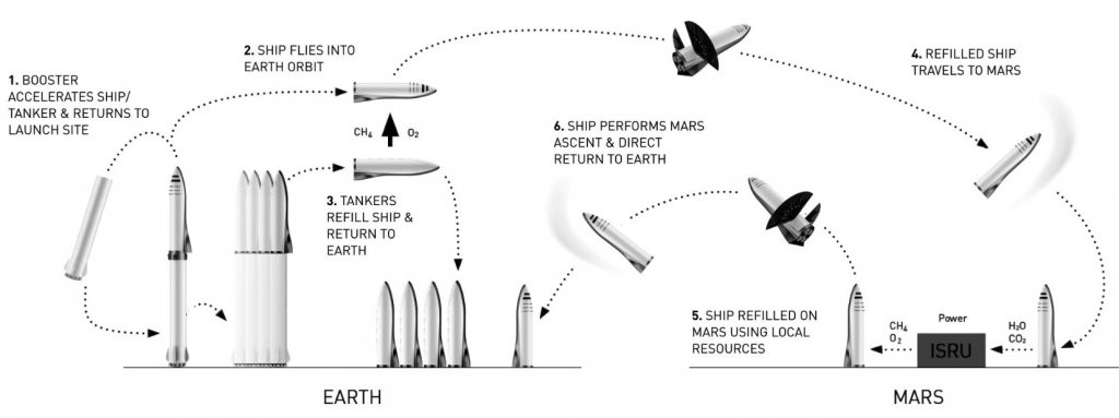
Elon Musk/SpaceX; New Space/Mary Ann Liebert, Inc. Publishers
A first-ever orbital test flight
SpaceX is working toward the vehicle’s first-ever orbital test flight, which the company wants to launch from its South Texas facility, called Starbase, at a quickly approaching date. However, for that launch to occur, the U.S. Federal Aviation Administration (FAA) has to complete an environmental review of the activities at Starbase.
That assessment was originally supposed to be finished by the end of 2021, but the FAA has delayed it on several occasions. It’s now targeting a May 31 submission.
That doesn’t mean that Starship has no mission planned.
In 2018, Japanese billionaire Yusaku Maezawa confirmed that he booked the vehicle to do a round-the-moon trip for 2023. Meanwhile, NASA chose Starship to be the first crewed lunar lander for its Artemis program in 2025, its mission that aims to explore the moon’s south pole.
‘Air Shield’ tech aims for virus protection on airplanes
Central WA firm’s ‘air shield’ tech aims for virus protection on airplanes
Play below for the audible version of this article:
Air travelers are returning to the skies and U.S. planes are now typically flying full and with many passengers not wearing masks — a worry for those most vulnerable to COVID-19 infection.
Pexco Aerospace, based in Union Gap in Central Washington, plans to offer a solution for airlines that could be ready to fly next year.
It has partnered with Seattle-based Teague, a leading design firm, to produce a simple snap-on plastic component that creates an “air shield” system it touts as increasing protection of airline passengers from virus transmission.
“There are still a lot of people concerned about air safety,” said Jon Page, president of Pexco. “We hope this will give people some peace of mind.”
Pexco, a unit of multinational aerospace conglomerate Transdigm, employs about 200 people in Union Gap, Yakima County, manufacturing plastic parts and trim for airplane cabin interiors, such as lighting and stow bin components and covers for the seat tracks.
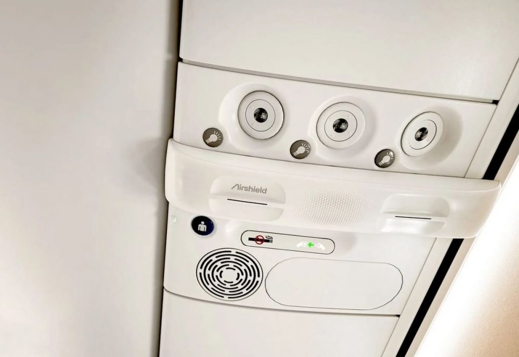

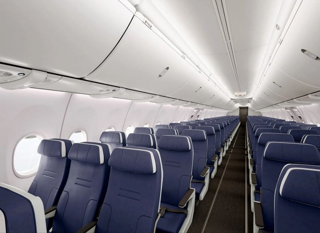
The new product, a concept developed by Teague in 2020, is a plastic component that fits over the overhead air vents above each row of passenger seats and redirects the air stream.
Instead of a cone of air flowing onto a passenger’s head from a pinhole above, several thin, curved slots in the plastic transform the flow into a curved “curtain” of fresh air that surrounds the passenger at the side and in front.
The idea is that air breathed out by the passenger, even a cough or a sneeze, will be directed downward by the air stream to the cabin’s outflow vents at the floor level.
Pexco said its tests show the system reduces shared air particles between neighboring passengers in an economy cabin by 76%.
It’s designed to be easily retrofitted to a Boeing 737 or an Airbus A320.
Page said Pexco has worked with Alaska Airlines and Southwest Airlines to develop and test the system and is in the final stages of getting Federal Aviation Administration certification.
He said with just a final smoke test to be completed the system could be certified this summer and installed on the first airliners next year.
Lockheed Martin tests new hypersonic weapon concept
The missile prototype cruised at five times the speed of sound ‘for an extended period.’
Play below for the audible version of this article:
A Lockheed Martin hypersonic missile prototype flew at five times the speed of sound “for an extended period” during a recent successful technology test for the U.S. military.
The hypersonic weapons test, which was announced April 5 by the Defense Advanced Research Projects Agency (DARPA), marked the second flight for the Hypersonic Air-breathing Weapon Concept (HAWC) program following a September 2021 test by Raytheon Technologies, DARPA officials said in a statement.
Program officials framed the new flight as a major milestone in the hypersonic program, which aims to conduct military operations at swifter speeds and with higher effectiveness compared to what’s currently available. “We are still analyzing flight test data, but are confident that we will provide the U.S. Air Force and Navy with excellent options to diversify the technology available for their future missions,” said Andrew Knoedler, DARPA’s HAWC program manager for the tactical technology office, in the statement.
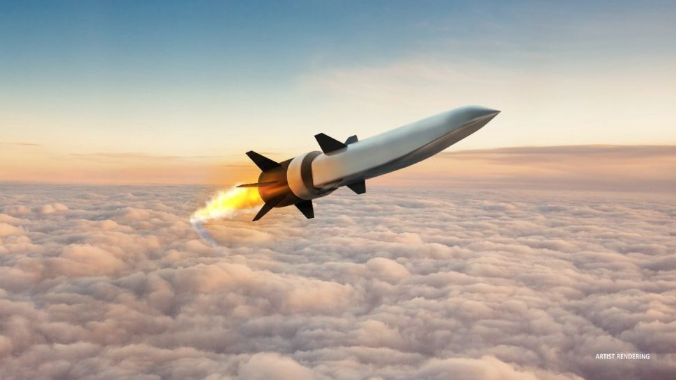
A press release from Lockheed noted the vehicle reached an altitude of 65,000 feet (nearly 19,812 meters), which is double the cruising altitude of a typical commercial flight. The vehicle will “address rapidly emerging threats in the global security arena,” John Clark, vice president and general manager of Lockheed Martin Skunk Works, said in his company’s statement.
DARPA and the U.S. Air Force are jointly working together on funding and supporting the HAWC program. Raytheon and Northrop Grumman together disclosed $200 million in funding for the project in 2019, while Lockheed Martin received nearly $1 billion in 2018, according to DefenseNews.com.
The program is seeking to assess feasibility, effectiveness and affordability across a series of flight demonstrations, and is by no means the first effort by U.S. military officials to work on hypersonic systems, either crewed or uncrewed.
A selection of other programs of hypersonic speeds include the 1950s-era X-20 Dyna-Soar that was designed to launch on a rocket, the FALCON hypersonic program (short for Force Application and Launch from CONtinental United States) of the early 2000s and Blackswift, which was later canceled.
How engineers are preventing icing on new types aircraft
Play below for the audible version of this article:
Weather conditions affect flight performance and safety and airframe icing is one of the most dangerous. Ice on airframes can cause severe aerodynamic and flight mechanical effects, significantly increasing the risk of flying.
How icing affects an aircraft’s performance and ways to mitigate the impact of icing on airframes is a major area of R&D. The recent improvements in battery technology are leading to new types of aircraft that need icing protection. Ice protection company CAV Systems’ engineering, product development and delivery vice president, Alexander Baty says, “There is more interest in urban air mobility. We are seeing a lot of interest from startup companies.
“Electrical power is obviously a precious commodity for those guys. It makes their options in terms of ice protection fairly limited.”
eVTOL aircraft and drone developers commonly use computational fluid dynamics (CFD) simulation tools during design to optimize airframes ahead of Type Certification.
“Typically in my laboratory we are improving the 3D CFD codes that are used by all the manufacturers, once they take a vehicle design to start the certification process,” says Steve McClain, mechanical engineering professor at Baylor University.
NASA’s LEWICE, (Lewis Ice Accretion prediction Code) was developed decades ago and became the standard ice accretion prediction code for certification analysis, especially for companies in the USA. LEWICE was first developed as 2D code, so only describes the air immediately above the airframe’s surface, the boundary layer (See box Lewice & Glennice).
McClain’s laboratory at Baylor University seeks to improve the fundamental knowledge of the ice accretion process and provide more accurate data for the CFD software.
“We are trying to capture the physics of icing in more detail so that manufacturers can have more confidence in predictions from LEWICE.
“With everything going to CFD nowadays, NASA is developing GlennICE, but it has a lot of other competitors in the field. There are other tools out there,” McClain says.
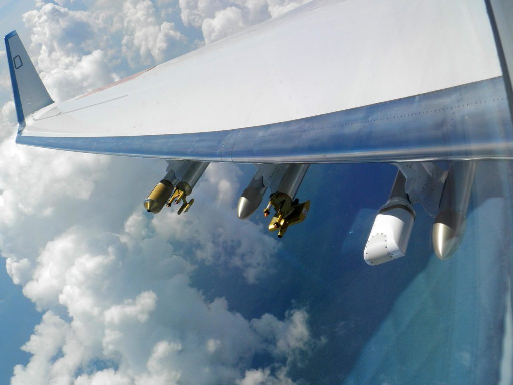
Another major effort to develop computer simulation tools for icing is the four-year European Union (EU) SENS4ICE project. SENS4ICE is expected to be completed next year with several flight tests. Some flight testing has already been conducted using a Russian Yakovlev Yak-42 aircraft which was carrying atmospheric test sensors.
The importance of icing research is underlined by the number and international range of partners SENS4ICE has. As well as the EU partners of Germany’s DLR and Italy’s Centro Italiano Ricerche Aerospaziali (CIRA), Russia and the USA are both participating in the project, while Honeywell and Collins Aerospace are also both involved.
Test equipment development
The aircraft testing equipment was developed during the first part of the project explains Carsten Schwarz, SENS4ICE coordinator. Schwarz leads the flight mechanics group at the DLR Institute of Flight Systems, Department of Flight Dynamics and Simulation. Super cooled large droplet icing is SENS4ICE’s focus and the project has several different approaches to testing for that.
“For this specific icing condition, we have quite a large number of sensors that are developed from different technologies. Some of those technologies have started at a very low technology readiness level and some were more advanced,” Schwarz says.
He explains that one of the technologies being used takes an optical approach. This detection technology is called shadography and involves the detection of droplets visually in images. Super cooled droplets are also important to McClain’s work at Baylor, which seeks to improve understanding of the physics of how droplets accrete on an aircraft’s surface.
“Once you have super cool droplets hitting the aerofoil, knowing the physics that happens on the surfaces and that freezing process and when it freezes is important knowledge. That’s what I’ve been doing for the past decade with NASA,” McClain says.
People may be surprised that icing is a problem that has not been solved, and McClain recognizes that it has been studied for many decades. He adds, “It is a really hard problem. It’s a multi-phase multi-species, transient non-equilibrium thermodynamics problem. Getting the amount of water that hits a specific location on the aircraft surface over a matter of a time is still a difficult computational task.”
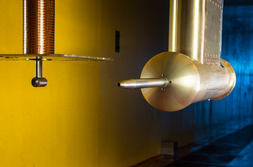
One of the testing technologies devised uses microwaves to measure the surface accretion.
Despite the widespread availability of super computing resources, the underlying physics that the test equipment is based upon is still limited.
“Most of the heat transfer measurements that I do at Baylor are still what are called dry measurements,” McClain explains. “So, we look at something like a scale roughness model and consider how that affects the dry heat transfer and make some assumptions about what goes on when you have a multi-phased situation on a real ice surface.”
The droplets are treated as having a “quasi equilibrium,” at a temperature near zero degrees Celsius. The quasi equilibrium means there is liquid, vapor and ice present. The phenomena occurring on the aircraft’s surface is that it absorbs what little heat is in the super cooled droplet and that droplet becomes an ice particle. As droplets strike the surface, or other ice particles, accretion occurs. Laboratory work focuses on better understanding that heat transfer process to be able to make better predictions for the simulation software.
Surface roughness
As the icing grows, the aircraft’s surface grows increasingly rough. “The roughness then affects the convective heat transfer,” McClain explains.
Characterizing the existing roughness, measuring the temperatures at the surfaces, measuring the developing roughness over time – the testing technology is needed to determine how the heat transfer is affected. To stop that accretion an established solution for airliners and other large aircraft is to use electrical heating. McClain sees more research going into icing countermeasures for eVTOL aircraft.
“Most of the research that I see today is all about the urban mobility-scale aircraft and the small air vehicles. And what do you do there? Quite frankly, the power excess to power the heating elements to get through weather is not as significant as a large commercial airliner,” McClain explains. The solutions that have been used for airliners and down to the size of general aviation’s two to four person aircraft have been electrical heating or fluids seeped onto surfaces.
However, eVTOL aircraft and drones, because of their small size, new designs and use of battery electric power supplies pose challenges to the use of most existing icing mitigation technologies on the market.
“We’ve looked quite significantly at electrothermal systems. They are used on the Boeing 787, but it was found that you need quite a large amount of electrical energy to provide full protection over the entire flight envelope,” says Baty. “We have done quite a lot of work on electrothermal systems, including work which has partially developed some capability ourselves, although we don’t have anything on aircraft.”
Fluid systems are an alternative to large electrical power requirements. While carrying a tank of anti-icing fluid would seem to be a problem for drones or eVTOLs with limited payload capacities, these aircraft do not fly for very long.
“With these aircraft, their flight endurance is low. We don’t need as big a tank of anti-icing fluid as on traditional aircraft. We’re seeing more interest from other areas. The first example would be military drones, things like the General Atomics Aeronautical Systems Predator B. We’ve done three or four different systems on those types of aircraft.”
For drones, CAV Systems is trying to miniaturize its product. “We’re looking at ways to distribute fluid around the airframe without adding weight to the systems and avoid pumps,” says Baty.
CAV Systems is aiming to flight test later this year a miniaturized systems on a commercially available drone which has a payload capacity of 12kg (26 lbs). Baty’s firm has also used icing wind tunnels (See box Creating icing conditions) in collaboration with partner organizations.
SENS4ICE is also using “several icing wind tunnels,” according to Schwarz. “All our sensors have been tested in icing wind tunnels.”
Sensors will be needed for the greater automation expected for icing systems. With no pilot aboard eVTOLs, even passenger carrying eVTOL services, and drones, the detection of ice and countermeasure activation needs to be automated. For airliners, the use of icing mitigation systems needs to be automated to avoid adding to the workload of a pilot.
“We’d really like to improve the capability of our autonomous system for eVTOL aircraft and OEMs like Airbus and Boeing,” says Baty.
Automation, detection, analysis, electrical heating or fluids, the mitigation of ice needs a variety of technologies all of which require further development as air transport advances.
Whether it is icing wind tunnels or Russian flying testbeds, the research work continues to solve this decades long challenge, which faces air transport old and new, piloted and autonomous.
LEWICE and GlennICE
NASA Lewis Ice Accretion Prediction Code (LEWICE) is a software program for predicting ice shapes, collections efficiencies, and anti-icing heat requirements.
LEWICE does not need a supercomputer, it can be run on a desktop computer, allowing users to run many parameter studies for their aircraft designs.
LEWICE models are used to calculate the ice growth rate at each point on the surface of a geometry. By specifying an icing time increment, the ice growth rate can be interpreted as an ice thickness which is added to the body.
This procedure is repeated, beginning with the potential aerodynamic flow calculations, until the desired icing time is reached. The ice shape predictions have been used to assess aircraft performance degradation both as an input to a CFD program or experimentally in flight or in a wind tunnel. The ice shape predictions have been validated against a wide variety of experimental conditions.
NASA Glenn Research Center is developing the software tool GlennICE to predict ice formation on aircraft and inside aircraft engines.
The goal for GlennICE is software that can accurately predict ice growth under any meteorological conditions for any aircraft surface.
The testing being undertaken for it is to understand the relationship between the roughness produced by the ice growth and the subsequent enhancement of the heat transfer creating the ice.
An extensive comparison has been performed against the ice shape database that has been generated in the Glenn Research Center Icing Research Tunnel.
Creating Icing Conditions
Icing wind tunnels allow researchers to create realistic realistic icing conditions to provide data on how effective ice protection equipment is and how ice adheres to any material.
The data from icing wind tunnels helps the development of ice accretion modeling tools. These are used by aircraft designers to assess the potential impact of ice on flight and engine performance.
Icing wind tunnels use ice spray bar modules and equipment to calibrate the chamber’s temperatures and ice produced by the bars. A spray bar module can have 50 nozzles producing the vapor cloud that will encounter the test piece. The modules, of which there can also be dozens, will be located many metres upstream of the test chamber itself. This distance is required for the spray bar’s cloud of droplets to become super-cooled even when the droplets are produced at a large size.
The tunnels temperature can go as low as minus 40˚C (104˚F) and a static pressure of up to 1.45 bar. The altitudes that can be simulate range from sea level to 23,000 feet and more. Such tunnel facilities can also have droplet tunnels. These are used to examine how droplets behave when the strike aircraft at high speed. The highly precise examination of droplets in air flow and how they deform and attach to surfaces can help researchers engineer surfaces to mitigate against accretion.
A new system could generate usable oxygen and fuel from lunar soil
Play below for the audible version of this article:
We’re edging closer to livable conditions on the moon.
Last year, an instrument on NASA’s Perseverance rover on Mars made oxygen from the Red Planet’s carbon dioxide atmosphere. Performed by Moxie – the Mars Oxygen In-Situ Resource Utilization Experiment – the strategy definitely incited hope for extraterrestrial survival. Future human missions could take versions of Moxie to Mars instead of carrying oxygen from Earth to sustain them.
But, Moxie is powered by a nuclear battery onboard. “In the near future, we will see the crewed spaceflight industry developing rapidly,” said Yingfang Yao, a material scientist at Nanjing University.
And, long-term survival on the moon shall be a turning point in manned deep space exploration. “Just like the ‘Age of Sail’ in the 1600s when hundreds of ships head to the sea, we will enter an ‘Age of Space.’ But if we want to carry out large-scale exploration of the extraterrestrial world, we will need to think of ways to reduce payload, meaning relying on as little supplies from Earth as possible and using extraterrestrial resources instead,” he continued.
Yao and Zhigang Zou, another material scientist at Nanjing University, explore whether lunar resources can be used to facilitate human exploration on the moon or beyond.
They published a study in the journal Joule, reporting that soil on the moon contains active compounds that can convert carbon dioxide into oxygen and fuels.
What does the moon have in store for us?
There’s no air to breathe on the moon. However, several elements such as argon-40, helium-4, oxygen, methane, nitrogen, carbon monoxide, and carbon dioxide have been detected in the lunar atmosphere.
While Earth-based spectrometers have detected sodium and potassium, the Lunar Prospector Orbiter found radioactive isotopes of radon and polonium. In 2012, the Lunar Reconnaissance Orbiter detected helium.
Meanwhile, the lunar regolith has been formed by meteorites’ constant impact, which has pulverized underlying coherent rock. All material sampled from lunar cores has shown evidence residing at the surface.
The layers of the regolith comprise meteorite, solar particles, and cosmic-ray bombardment. And the exposed surface layers contain implanted solar material such as rare gases and elements transported from the sun in the solar wind. In rocks of the moon, oxygen is the most abundant chemical element.
Here, Yao and Zou hope to design a system that employs lunar soil and solar radiation, the two most abundant resources on the moon. Their team analyzed the lunar soil brought back by China’s Chang’e 5 spacecraft and found the sample to contain compounds such as iron-rich and titanium-rich substances that could work as a catalyst to make desired products such as oxygen using sunlight and carbon dioxide.
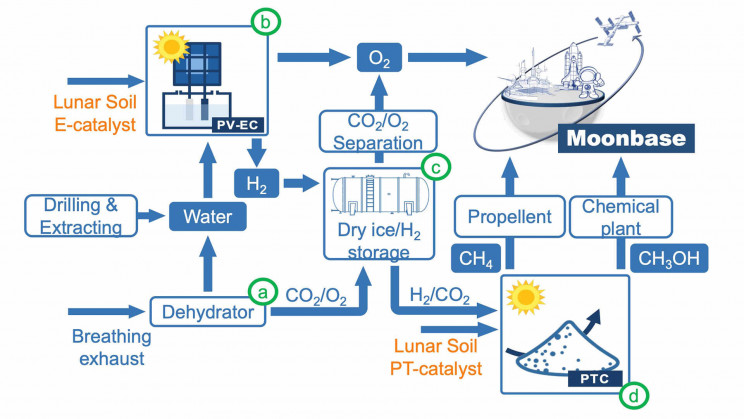
The proposed strategy? “Extraterrestrial photosynthesis”. The system would use lunar soil to electrolyze water extracted from the moon and into astronauts’ breathing exhaust into oxygen and hydrogen-powered by sunlight. The carbon dioxide exhaled by moon inhabitants would also be collected and combined with hydrogen from water electrolysis during a hydrogenation process catalyzed by the lunar soil.
This process generates hydrocarbons such as methane which could be used as fuel.

Extraterrestrial survival is close
According to the researchers, the strategy utilizes no external energy but sunlight to produce water, oxygen, and fuel – desired products that could support life on a moonbase. The team is currently looking for an opportunity to test the system in space, likely with China’s future crewed lunar missions.
“We use in-situ environmental resources to minimize rocket payload, and our strategy provides a scenario for a sustainable and affordable extraterrestrial living environment,” Yao said.
Though the catalytic efficiency of lunar soil is less than catalysts available on Earth, the team is testing different approaches to improve the design, such as melting the lunar soil into a nanostructured high-entropy material, which is a better catalyst, Yao said.
Lunar soil or the components extracted from lunar soil can essentially reduce the load and cost of a spacecraft, thereby improving the feasibility and durability of human survival with ‘high economic efficiency, giving high hopes to future manned missions.