1 – Introduction
2 – Aerodinamic for compressible gas – Basic principles
4 – Turbogas cycle
5 – Turbofan
5.1 Turbofan with separated flows
5.2 Turbofan with associated flows
6 – Combustion chamber
7 – Inlet
8 – Nozzle
9 – Turbine Engine
The dynamic intake is the first component that meets the flow in its evolution through the engine. It is positioned to provide the minimum external resistance. The task of the air intake is to channel the flow at low velocity throught the compressor (or to the combustor in the case of the ramjet) without causing the detachment of the boundary layer (because by the slowdown of the flow, the static pressure increases, and the flow is then submitted an adverse pressure gradient). The air intake must be designed to provide the engine the required flow rate and also so that the output of the dynamic intake flow entering the compressor is uniform, stable, and with “good quality”. So the goals of the Inlet are:
- – slow down the flow (up to M = 0.4 to 0.5);
- – increase the pressure;
- – uniform flow at the upstream of the compressor;
- – minimal loss of total pressure;
- – minimum aerodynamic disorder;
- – minimum weight (ie minimum length).
The performance should not be prejudice in the presence of an incidence angle or yaw. It is useful to observe that the requirement that the flow is uniform before the compressor could be more important than to have small total pressure loss. The inlet is essentially a duct where the air flows in stationary conditions. it is designed according to rules of gas dynamics; since such laws have different implications depending on how the flow enters in the duct, if in supersonic or subsonic conditions, the main classification of distinguishes between:
- – subsonic inlet;
- – supersonic inlet
- Subsonic Inlet
The subsonic Inlet is an important component, since all the civil turbojets and commercial aircrafts have air vents of this type. The first characteristic that must have an subsonic inlet to slow down the flow can be derived from the equations of the stationary quasi-one-dimensional flow:

As known, this report implies that in the conditions of flow isentropic (dFattr= 0) and subsonic flux (M <1) for an increment of area corresponds to a slowing down of flow and a increment of static pressure. The aim of the Inlet is to slowing down the flow, therefore its shape is divergent. In the real case (non isentropic) has to be considered the term dFattr, which as it determines an increment of M (if M<1), to obtain the same variation of M is necessary to use magior variation of area. The one-dimensional study allows to study the variation of area but does not provide any information about the length of the dynamic. The aim is to reduce the length of the Inlet as more as posible to reduce the weight and to minimize the losses of total pressure. The relation between the total pressure and the length of the duct is expressed by this formula:
Thus the losses of total pressure is proportional to the length. The multidimensional study instead indicates that due to the existence of a boundary layer in the presence of adverse pressure gradient, is necessary to consider long duct to get small pressure gradients to avoid the possible risks of separation. In fact in case of separation, would have greater losses of total pressure, a not uniform flow, and a reduction of the effective area ratio (the part near to the wall, due to separation, will not follow the geometric area ratio).
To avoid the separation is necessary that the pressure gradient has to be lower than a value (Dp / dx)max, which it is typically determined experimentally, beyond which the tendency enhances to the separation.
In practice, if we consider a dynamic subsonic Inlet with conical shape, it has been observed by experimental studies that the maximum half-opening cone angle that can be considered is of 10 degrees. Obviously this value can be different depending on the area ratio considered, and generally are adopted angles between 5 and 7 degrees. The ideal condition is that with an undisturbed air flow in entrance to the Inlet, thus M1=Ma, in this case the thermodinamic variables are equal to the enviromental ones. Generally this condition is not satisfied. Thus the external “flux-tube” will assume different shapes (divergent or convergent, with different area ratios, see figure below).
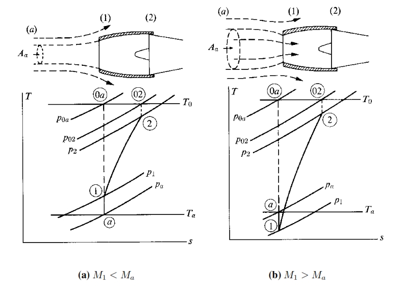
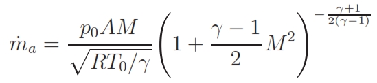
By knowing the altitude and the speed (for the hypothesis of isentropic flux, T0 and p0 are constant) and the flow rate ma requested by the engine, can be used this relation to calculate M1 by replacing A with A1 (entrance section of the Inlet) and M2 by replacing A with A2 (exit section of the Inlet):
From the flight Mach number Ma is possible to calculate the section of tube at infinite (at upstream), the so called “catching area” Aa. Thus M1 can be different with respect Ma. Whether M1 < Ma (for example at low speed or low flow rate) the flux tube at upstream of the Inlet is also divergent (see figure below). At low speed (or for high flow rate, that occurs at take off and in climbing fase) M1>Ma, that means the flux at upstream is convergent and the speed becames maximum at entering section A1 of Inlet. Aa>A1 implies that the flux accelerates externally, thus nullifying the aim of the Inlet that is to slow down the flux, while Aa<A1 it has to be avoided because causes an increasment of the drag. The ideal condition is Aa=A1.
- Performances
The parameters by means the efficiency can be calculated are.
– Ratio between the total pressures:
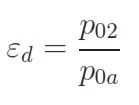
– Adiabatic efficiency:

with:

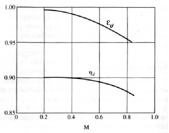
In the figure below is highlighted that the efficiency εd (as conseguence also the ηd) decreases with the increasment of Mach number.
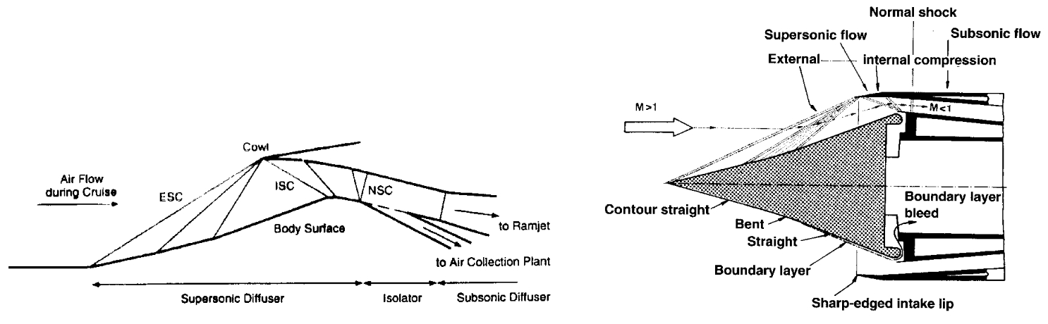
- Supersonic Inlet
Even in this case the Inlet has to slow down the air that enters in the engine at flight speed untill the subsonic velocities (around M=0.3 -0.4) requested for the compressor (or for the combustor). By means the relation for a quasi-monodimensional isentropic flux (M>1, dFattr=0), valid for an supersonic ideal diffuser, is observable that the duct has to be convergent to be able to slow down the flux, while for a subsonic ideal diffusor, it has to be divergent. Afterward it has slowed down the flux till M=1 with a convergent duct, the deceleration has to be done by means a divergent ducts (see figure below).
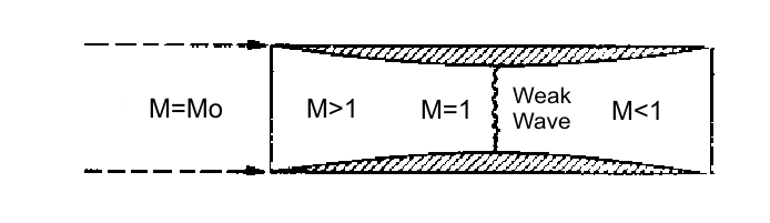
The isentropic solution to decelerate the flux from supersonic to subsonic therefore is a conduct convergent-divergent. Once the fligth project mach number Ma is fixed, is fixed the geometry as well (the ratios A1/At and A2/At since M1=Ma, Mt=1 and M2 is equal to the value requested by the compressor. But this solution is only applicable theorically. Infact an Inlet with this solution is not possible to made up, because in the starting phase (when the Mach flight number is lower than Mach number of project) the areas ratio (between entering and throat) would be excessive, for which the flux reach an unitary value of Mach number before to reach the throat, this is not acceptable (the flux velocity is too slow). In this case there is a shock wave due to the excessive air flux in the entrance, that remove the assumpthion of iso-entropy. To obtain the desired performance, it is necessary to reach a Mach number higher to the project Mach till to “swallow” the shock wave, afterwards it is possible to decrease the velocity; this method is called “overspeeding”. Alternatively it can be used an Inlet with variable geometry. The shock waves can not be avoided because the Inlet has to be able to work for several flight conditions, for the weight and encumbrance reduction. The most important solution are listed below:
- – Pitot Inlet (with normal shock wave)
- – Inlet with oblique shock wave and external compression
- – Inlet with oblique shock wave with mixed compression external/internal
Pitot Inlet (with normal shock wave)
This Inlet is the most simple and light. It an divergent Inlet that in supersonic flight condition determine ahead a normal shock wave. The presence of this shok wave cause a loss of total pressure that can be calculated by this formula:

This solution is preferred with Mach number slightly supersonic, M ≃ 1.7 ÷ 1.8. With M≤1.5 the losses of total pressure caused by the normal shock wave are lesser than 10%, and are higher for values of M higher. When the Inlet doesn´t works within the project operating conditions the flow rate requested by the engine is different with respect the aspected one (fig 1a). If the requested flow rate is lower than the project one the losses of total pressure do not change and the Inlet draw off the excess air due a “stave off” of shock wave toward outside (fig 1b). It is necessary to avoid the super critical opereting condition when the flow rate is bigger than that requested by the project. In this case the schok wave moved internally with a decreasment of total pressure p0 and therefore with decreasment of flow rate elaborated by the engine (because ṁ=Г·p0·At / (R · T0)1/2).
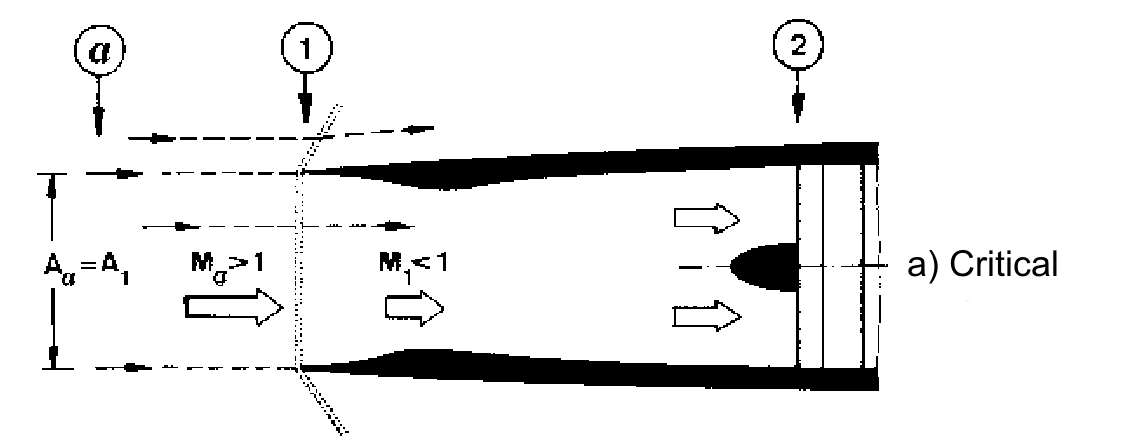
Fig (a)
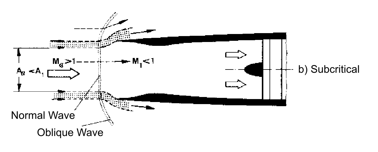
Fig (b)

Fig (c)
Inlet with oblique shock wave and external compression
The oblique shock wave has lesser intensity with respect the normal one. The compression occurs by means one normal shock wave or by N oblique shock waves (this esemble has the same intensity of the normal one) and it gives higher pressure ratios ε, with more shock waves N (ε -> 1 with N -> ∞, iso- entropy compression, see figure). Nevertheless by increasing the numbers of shocks the direction of the flux, that outcoming from the ramps, is more sloping with respect the axial direction. That means the losses are more high in subsonic part of fluxes, which serves to bring back the flux in the axial direction. By this consideration it is possible to determine an optimum number of shocks according to the Mach flight number. Hence this kind of Inlet are used mainly for supersonic field. Since the compression occurs externally, in this case the flux is more adaptable for different flight condition, and thus the common problem of starting for a convergent – divergent Inlet can be avoided.
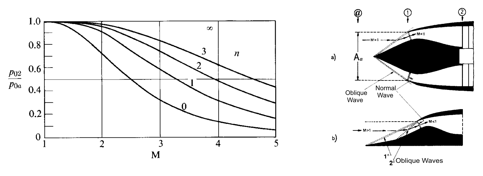
Inlet with oblique shock wave and external/internal compression
As already mentioned above the length of Inlet and the rotation angle of flux (therefore weight and encumbrance) increase with the increment of the number of shock waves. The external compression can bring too wide rotations of flux, consequently losses in terms of internal strength. To avoid this inconvenient it is possible to use an Inlet with a mixed compression, wherein occurs an deceleration of flux by means a convergent duct, but whitout to reach a Mach number not unitary; afterwards the flux is decelerated by ramps that induces oblique shock waves.