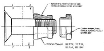
The phenomenon of inter-rivet buckling occurs when there is a localized buckling or instability of the panel (or of the flange of the stiffener) between two consecutive rivets, it can occurs if the panel is stressed in compression.
In order to prevent this phenomenon, the compressive stress in the panel (or in the flange of the stiffener) will be limited to a value that will be defined as allowable stress.
- Assumptions
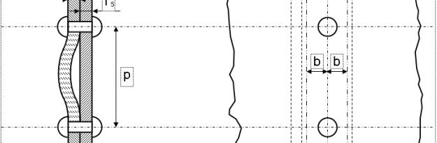
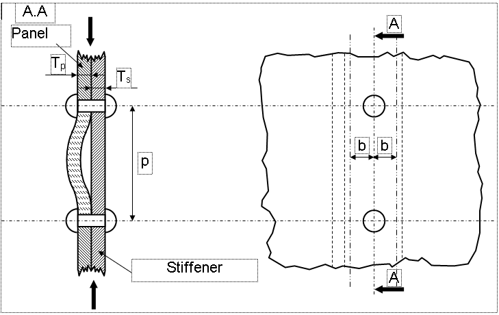
We consider a sheet metal strip (Stiffener) with width 2b is jointed to a panel.
- Critical Stress
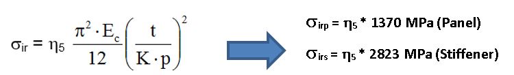
The allowable stress for Inter-rivet buckling can be calculated by the following formula:
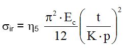
With:
• Ec: compression modulus of the material (normally the minimum one is used between the parts attached).
• ƞ5: plasticity correction coefficient, it is equal to: ƞ5 = Et / Ec
• K: coefficient that depending on the type of fasteners used
• p: pitch that is axial distance between rivets
• t: thickness of the attached elements considered (Panel, Stiffener, etc.)
Tests have shown that depending on the type of fasteners, the binding conditions at the ends of our column change. The boundary conditions are between the hinged (K = 1) and constrained condition (K = 0.5).
For example for bolts, the usual value is K=0.50.
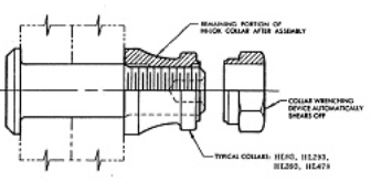
Instead for bolts or rivets instead the value is K=0.65.
- Numerical Example
The junction between stiffener’s flange and a panel is ensured by countersunk screws with a pitch=22mm; below are reported the data for the calculation:
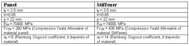
By considering the formula explained above, the Inter-rivet buckling allowables for each part are:
For the panel, the plasticity correction coefficient is calculated as follows:
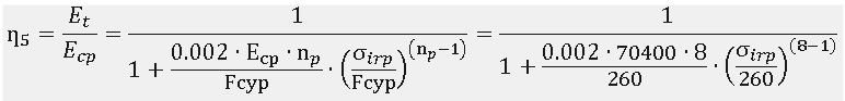
With:
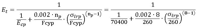
Therefore:
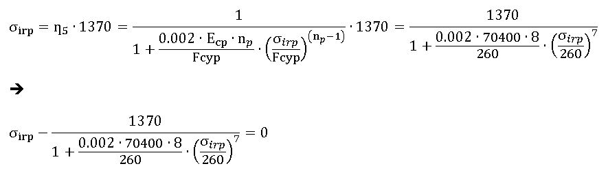
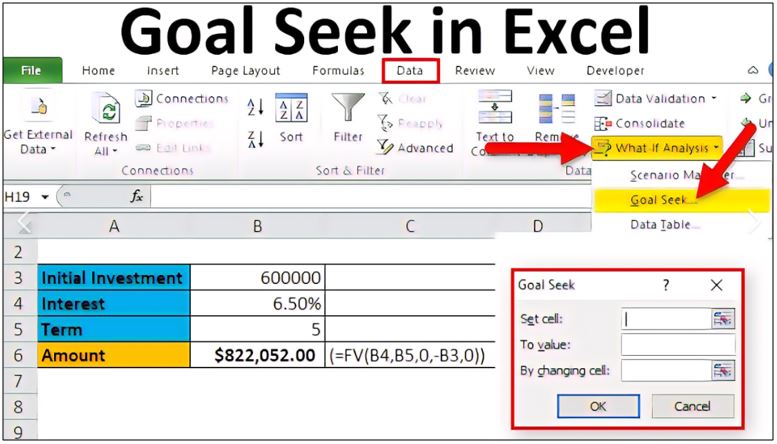
In order to obtain the equivalence reported above, you have to carry out a numerical iteration; it can be done easily by “Goal Seek” function of Microsoft Excel, see below how:
Set the following parameters (see figure below):
- “Set cell” = equation reported above
- “To value” = 0
- “By changing cell” = link to cell to cell where you set an initial value for σirp (for example to 200 MPa)
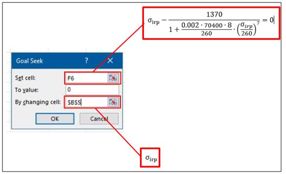
Then click on “OK”, and you will get the final value for the allowables.
So final values for inter-rivet buckling allowables for panel and stiffener are:
σirp =259.55 MPa
σirs =439.38 MPa
Usually is taken the minimum between the σirp /σirs and Fcy as allowable. This allowable is compared with the maximum compression stress of attached parts.