The significance of residual stresses for fatigue is important in various practical problems. Unintentional tensile residual stress can have an adverse effect on the fatigue resistance, while compressive residual stress can significantly improve the fatigue behavior. Residual stresses can be present in a material as a result of different processes. The main ones are listed below:
(1) Inhomogeneous plastic deformation, in many cases at notches
(2) Production processes
(3) Shot peening
(4) Plastic hole expansion
(5) Heat treatment
(6) Assembling components
- Inhomogeneous plastic deformation
A simple theoretical model will be discussed first. In figure below two tension bars of different lengths are connected to the same infinitely stiff clampings at the ends. If a load is applied to this 2-bar system, the elongation Δl is the same for the two bars. As a consequence, the strain ε in the shorter bar will be larger because its length is shorter. In view of the larger ε, the stress will be higher and the bar thus will carry more load than the other bar. This is shown in the load-displacement diagram in figure below. There is a
load concentration in bar 1. Assuming that both bars are similar, it implies that permanent plastic deformation can occur in bar 1, while bar 2 is still fully elastic.
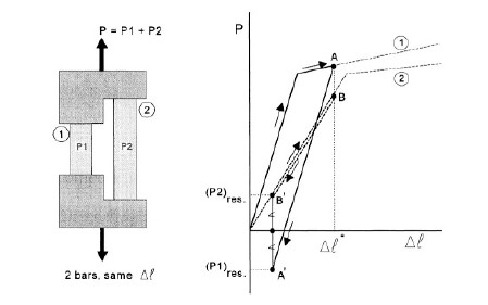
This occurs at points A and B where Δl = Δl*. During reversion of the loading direction elastic unloading occurs in both bars, from A to A’ in bar 1 and from B to B’ in bar 2. After full unloading P = 0, which means that the sum of the residual loads in the two bars is zero; and thus (P1)res = (P2)res, see figure above. Because of the plastic elongation of bar 1, this bar is longer than it was before. As a result, it will be in compression at P = 0 while bar 2 will be in tension.
Residual stresses have been introduced as a result of plastic deformation in one part of the 2-bar system.
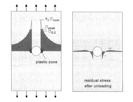
A similarly inhomogeneous plastic deformation occurs in a strip with a hole loaded in tension, see figure below. If a high load is applied to the specimen, σpeak at the edge of the hole exceeds the yield limit, and a small plastic zone is created at the root of the notch. As a consequence of the plastic deformation, σpeak is smaller than Ktσnom. The peak of the stress distribution is flattened by local plastic yielding. In the plastic zone permanent plastic deformation has occurred. The plastic zone is elongated; it is larger than it was before. After removing the tensile load on the strip, i.e. in the unloaded condition, the elongated plastic
zone will be under compression. It does no longer fit stress-free in the elastic surrounding which tries to constrain the permanent plastic deformation. A residual stress distribution is introduced with a residual compressive stress at the root of the notch, which is the fatigue critical location under cyclic loading. The residual compressive stress is balanced by residual tensile stresses away from the notch. The residual compressive stress at the root of the notch can be very favourable for fatigue. In general, local plastic deformation causes an inhomogeneous residual stress distribution as illustrated by the right hand picture in figure below.
- Production processes
Two common production processes are cold working and machining. Cold working implies that the material is plastically deformed, which should leave a residual stress distribution in the product. An elementary example is plastic bending. As illustrated by figure below, a bending moment will induce plastic deformation in the outer fibers of the material. After unloading, elastic spring back occurs, and a residual stress distribution as schematically presented in figure below will remain in the material.
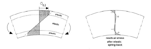
In a similar way, residual stresses can exist after a variety of cold working processes. Forging in many cases is a hot-working process, which still can leave residual stresses. The same is true for rolling of some product forms starting at an elevated temperature. Rolling for sheet straightening is done at room temperature. Rolled sheets and plates may carry a residual stress system.
It is not always realized that machining operations can also introduce residual stresses. Metal cutting implies removal of a layer of material, which includes a failure process near the tip of the cutting tool. But the failure process is preceded by plastic deformation. Depending on machining conditions (sharpness of the cutter, feed rate, depth of cut, etc.) and the material, residual stresses can be significant, although they only occur in a thin surface layer.
- Shot peening
Shot peening is a well-known process to introduce favourable residual stresses in the material surface of a component. In various practical cases it is applied to prevent fatigue or stress corrosion problems. The peening operation implies that the surface layer of a material is plastically stretched by blasting hard particles (shot) onto the surface of a component. Because this layer must remain coherent with the elastic substrate material, residual compressive stresses are introduced at the surface. It can lead to warpage of the component, although dimensional distortions can sometimes be prevented by a symmetric peening operation.
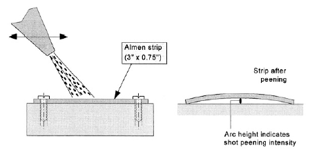
The intensity of the peening operation can be checked by peening a so-called Almen strip, which is a steel strip (3″×0.75″, 76mm x 19mm). The strip is fixed by bolts to a stiff foundation, and peened under well defined conditions from one side only, see figure below.
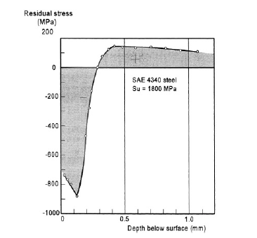
After removing the bolts, the strip is curved. The arc height is measured, which gives a direct indication of the shot peening intensity. An example of a residual stress distribution obtained by shot peening is shown in figure below for a high strength steel, which is fatigue sensitive. Surface rolling is another process to plastically deform the material surface. It can be applied locally to the notch root area, e.g. to the root of a fillet radius.
- Plastic hole expansion
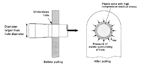
Plastic hole expansion has been developed to improve the fatigue resistance of holes, also for bolted and riveted joints. The hole is drilled with a slightly undersized hole (a few % too small). A tapered pin is then pulled through the hole to expand the hole, see figure below. As a result, plastic deformation does occur around the hole. The plastic zone has been stretched tangentially and pushed outwards in the radial direction. The plastic zone has a larger diameter than before. It implies that the elastically strained material around this plastic zone will exert a pressure on the zone, see figure below, which causes tangential residual
compressive stresses around the hole. The method is very effective for improving the fatigue resistance because the residual stresses can be high, i.e. almost in the order of the compressive yield stress. Moreover, the depth of the plastic zone can be a few millimeters (compare to the small depth in figure above). Small distortions of the cylindrical shape of the hole can be corrected afterwards by reaming, which hardly reduces the residual stress.
Commercial apparatus has been developed for hole expansion, and a large favourable effect on fatigue can be obtained.
- Heat treatment
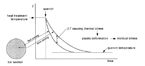
Quenching is an abrupt step of many heat treatments applied to alloys of various materials. Cooling usually occurs very fast at the outside of a component, see Figure 4.8, and significantly slower inside the material. The inhomogeneous cooling introduces thermal stresses. The faster thermal contraction at the outside causes local tensile stresses balanced by compressive stresses inside. At the still elevated temperature, the yield stress is low and plastic deformation can easily occur. Residual stresses are then introduced.
In the rotational symmetric case of Figure 4.8 it should lead to the favourable situation of compressive residual stress at the outside balanced by tensile residual stress inside the material. Unfortunately, many components have complex shapes which makes it difficult to know the residual stress distribution obtained after quenching. Tensile residual stresses, also at the outside, are possible. They can be reduced, or even reversed, by shot peening.
- Assembling stresses
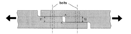
The previous examples of sources of residual stresses were associated with inhomogeneous plastic deformation. A completely different category of residual stresses in a structure is due to assembling of components to form a single structure. In many cases, bolted connections are involved (also welding). The residual stresses in the structure depend on the dimensional tolerances of the components. A simple example is shown in figure below. If t1 and t2 of this joint are not exactly equal, and the bolts are fastened, the misfit will introduce bending. Maximum internal stresses occur at the root of the fillet notches A in figure below in the still unloaded joint. In this case the term “internal stresses” appears to be more correct. These stresses due to assembling a structure are also referred to as built-in stresses. The occurrence of the stresses can be avoided by a strict tolerance system.
In special cases, built-in stresses are desirable. This applies to bushes pushed with an interference fit into a hole, and to prestressed bolts.
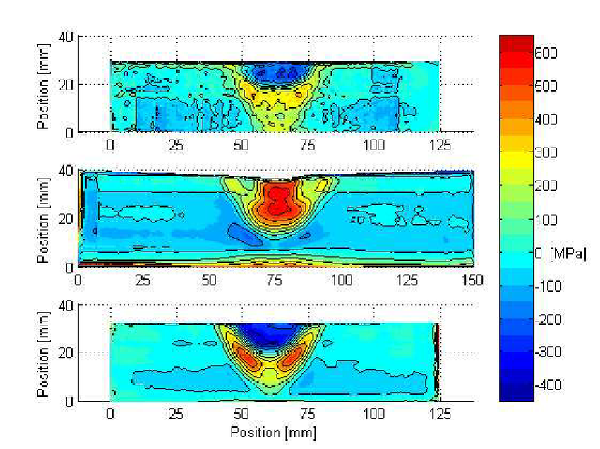
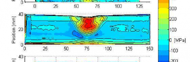
Below instead is shown welded residual stress distributions measured by the contour method.