One of severals potential design under study by Boeing and Nasa, is the transonic truss-braced wing (TTBW) concept. The concept, which is in the running to be tested as a piloted X-plane in the early 2020s, derives its high lift/drag efficiency from its slender, glider-like wing. In the version most recently tested, the TTBW has an aspect ratio (wingspan squared divided by area) of 19.55 (it´s 11 for the composite-wing Boeing 787 and 8 for the conventional-wing 747-400).
Originally designated simply as TBW, NASA recently added “T” for transonic (range of Mach 0.8 to 1.0, i.e. 965–1,236 km/h at sea level) to emphasize the unusual high-speed capability of the concept, and to differentiate it from the similar looking but radically different slow-speed, strut-configured general aviation aircraft.
Compared with a conventional cantilevered wing, a truss-braced wing can theoretically be lighter because the load is partially shared with the strut, relieving some bending moment. The wing structure can therefore be lighter, enabling a larger wing for the same weight. The larger the wing is, the bigger the potential lift-to-drag ratio and the lower the induced drag. Struts also allow thinner wing profiles, significantly reducing drag and making it easier to fly at transonic speeds. The thinner profile is also more suitable for natural laminar flow, reducing the zero-lift drag and further enhancing efficiency.
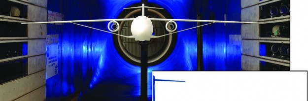
Boeing and NASA have been validating the concept over three phases of tests, the most recent of which was completed in February at the Unitary 11 X 11-ft. transonic wind tunnel at NASA Ames Research Center in California. Phase 1, completed in 2010, had indicated that a TTBW design could reduce fuel consumption by 5-10% over a conventional cantilevered wing. While the numbers from Phase 1 looked promising, researchers were still unsure about the critical question of the weight of the wing. To give the thin wing structural margin against flutter, the potentially catastrophic aeroelastic coupling of aerodynamic loads with structural modes, the weight penalty would threaten to outweigh the fuel-burn benefits. To obtain more accurate weight estimates and validate a structural model, Boeing therefore developed a finite-element model of the configuration and worked with Georgia Tech and Virginia Tech to wind-tunnel test a dynamically scaled model of the “Sugar High” TTBW.
Phase 2 tests were conducted on a 15%-scale half-span model in NASA Langley Research Center’s Transonic Dynamics Tunnel in 2014-15 and, to the surprise of some, confirmed that despite the lower stiffness of the inboard wing compared to a conventional wing, the flutter weight penalty was acceptable. Testing was conducted in the NASA Ames tunnel on a 4.5%-scale model with a 12.5-deg. average sweep and7.7-ft. wingspan. At full scale, this would represent a span of approximately 170 ft. compared to almost 118 ft. for a winglet-equipped 737-800. As per Greg Gatlin, a research engineer of NASA, the main issues is the flow as it goes between the wing and strut. As they come together, there is interference and one influences the other, so a shock can set up in there and cause drag.
By using computational fluid dynamics, the NASA’s engineers hope to minimize those effects in this particular shape, also by using pressure sensors and pressure-sensitive paint to see if there are separations and other flow phenomenon going on that maybe the computations haven’t captured. The goal is to avoid the separation of flows caused by the presence of the strut interacting with the bottom of the wing, and also to assess an appropriate amount of load, which will drive thicknesses and shapes as well.
Two truss designs were tested, both sharing common mounting locations at the fuselage and underside of the outboard wing. The baseline strut attaches directly to the lower surface of the wing at an acute angle; the alternate design is offset from the wing interface to enable the outer end of the strut to connect to the wing perpendicular in a pylon-like attachment (see figure below). Both struts were designed to generate “a little bit of negative lift,” because there is too much flow goes through the gap between the wing and the strut, it could generate a shock.
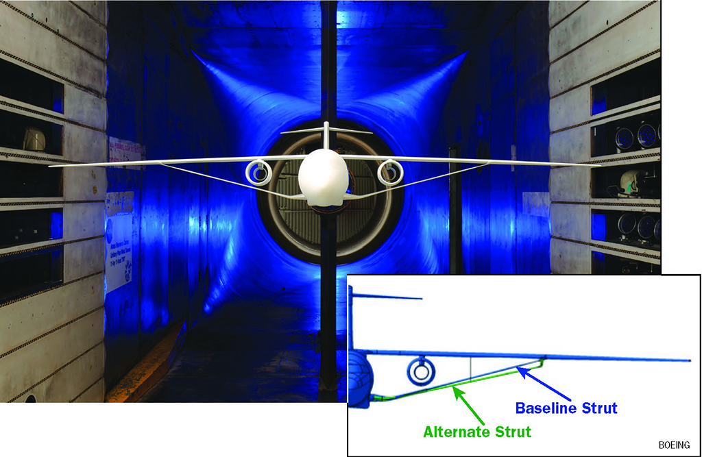

Testing revealed very little difference between the two options. The alternate strut shows slightly higher drag at the design point, but it may be better in terms of operability.” The wing-to-strut connection is the same pin connection mechanism in both to prevent bending, and to handle compression and tension loads.
High-speed testing included a wide range of speeds above and below the design point. The tests have been carried out from cruise condition, by testing for some operating margin above that to Mmo [maximum operating Mach], with Mach 0.795, and beyond that to Md [dive-speed Mach], with Mach 0.865, it was also tested at speeds down to at least Mach 0.5.
To help track the deformation, a series of dots was located on the model and filmed by two dedicated cameras. The dots on the fuselage are for reference, assuming that [the fuselage] won’t deform, but there are six rows of dots on the wings, which will help us determine the deflection of the wing both upward and in twist. The model is very rigid with the struts on. The struts are not as good at controlling the twist as they are for stiffening, but it still does have a contribution because part of it is to get a favorable twist with load. NASA and Boeing are discussing options for a potential fourth test phase since there are a lot of thing not yet investigated, like studies regarding damage tolerance and bird strike.
[smartslider3 slider=”2″]