
Access to space is becoming easier and currently one can launch small spacecraft into Low Earth Orbit (LEO) for a few hundreds of thousands of dollars. According to the U.S. Space Surveillance, there are half a million space objects in Low Earth Orbit (LEO), and only 30,000 are actively tracked. 23,000 pieces of orbital debris are larger than 10 cm and provide more velocity when in orbit. The estimated population of particles between 1-10 cm in diameter is approximately 500,000. There are 100,00,000 pieces of debris that are smaller than 1mm. The United States is responsible for 30% of all orbital space debris. The debris is frequently in transit the orbits of hundreds of operational spacecrafts. Additionally, most of the debris were inserted into long-duration orbits, with orbital lifetimes imagined at multiple decades and centuries. Collisions can lead to huge investment efforts, including expensive fixes. There have been three major collisions since 2005. They all involve a large intact body, typically a satellite, colliding with smaller pieces. With these smaller pieces still in orbit, more collisions will occur, thus creating more space debris. The term “debris removal” implies taking active measures to remove something from orbit and not letting its orbit decay on its own. There are three main removal technology concepts: Laser Solutions, Electrodynamic Tethers, and Deployable Nets.
Active orbit debris removal
De-orbiting of the debris is mainly focused on using different mechanism for changing orbital velocity. This is done by applying a force (or impulse). In the limiting case where the orbital velocity is reduced to zero, the object will only have gravitational potential energy and, thus, “fall” back to Earth. The three technologies considered are different in the way they impart this force or impulse. The lased-based approaches impart this force or impulse in a contactless fashion. Electrodynamic tethers are objects that are deployed from or attached to an object that will result in forces being applied to it form Earth magnetic field. Nets apply this force by physical contact with the object.
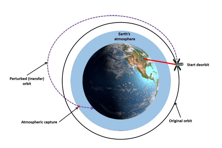
As depicted in figure below, all three of the orbital debris removal systems discussed here effectively perturb the original orbit of the object so that it eventually gets captured by the atmosphere.
Laser Orbital Debris Removal (LODR)
Laser orbital debris removal (LODR) is a contactless method in that applying a force or impulse to the object to be de-orbited does not require to physically contact it. The system uses a laser either on Earth or in orbit to shone on the object that is to be deorbited. One of the earliest proposed use of LODR was by NASA in 1996 with Project Orion. Project Orion [1] was created as a “laser broom” to remove all pieces of debris less than 10 cm under 1100 km in two years. This LODR as used a pulsed laser.
The LODR solution is considered successful, especially for larger debris. With having the ability to capture debris from the ground and in space, researchers can explore a solution with multiple options. There are concerns with this laser orbital removal technology capturing the smaller pieces (less than 1mm).
As depicted in the figure below, the laser, which is either a ground- or space-based one applies a force or impulse to the debris. This in turn changes the orbital speed and eventually orbital radius “r”.
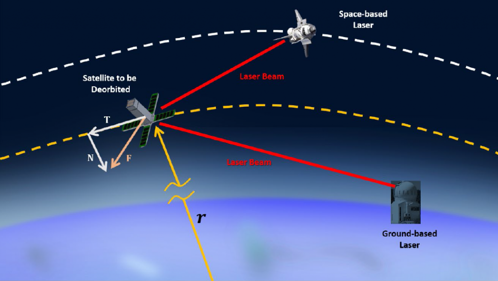
The total force imparted to the debris is F and can be resolved into its tangential component T and radial/normal component N. As will be discussed below, the magnitude of T and N depend on many factors including the orientation (attitude) of the debris. The force applied by the laser beam causes a change in the debris orbital velocity which puts it into a transfer orbit with a perigee deep in the dense part of the atmosphere ash shown in Figure 1.
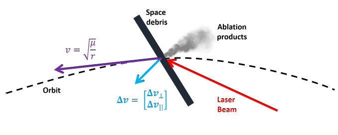
The laser deposits energy into the material of the debris which causes ablation of the material. The ablation products leave the debris at a high speed and carry with them some of the momentum of the debris. In effect, the ablation products are acting as a miniature thruster that is applying an impulse to the debris. The net thrust that is imparted by the ablation products depends on the orientation of the debris. As show shown in Figure above, if the flat part on which the laser shines is not perpendicular to the original velocity vector, the resulting force will have both a tangential component T and a normal component N.
Referring to Figure 3 above, the magnitude of the tangential velocity change |Δv| applied to the debris is described by the following equation:
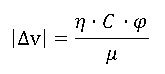
The efficiency factor ƞ accounts for the combined effects of improper thrust direction on the target, target shape and tumbling. The term φ is the laser fluence which is a measure how much energy is contained in the laser. The mechanical coupling term C measures how much of how effectively the laser energy is converted into momentum change of the debris. The last term in this equation μ is the debris areal mass density and is a description of the debris’ geometry.
The equation above shows, the change in orbital velocity achieved by LODR depends on many factors including the laser being used as well as the geometry and construction of the debris’ host spacecraft.
Below are reported the characteristics of LODR on common materials used on spacecraft ([2], [3]).
| Debris Material | Laser Fluence Required (J/m2) | Mechanical Coupling Coefficient |
| Aluminum (Al) | 11.7 | 3.94E+29 |
| Gold (Au) | 16.9 | 2.20E+36 |
| Carbon (C) | 15.68 | 3.20E+27 |
| Iron (Fe) | 13 | 1.19E+32 |
| Lithium (Li) | 10.4 | 1.05E+23 |
| Molybdenum (Mo) | 5.2 | 5.46E+36 |
| Tungsten (W) | 20.8 | 2.48E+38 |
Below are reported the Advantages and Disadvantages of LODR
Advantages:
- Contactless, no interaction with space debris
- lasers can work with most materials commonly used (see tab above)
Disadvantages:
- Difficulties to be aware on the orientation of the debris (required for tangential velocity change)
Electrodynamic Tethers (EDT)
Electrodynamic Tethers (EDT) are systems that take advantage of Earth’s magnetic field to generate an electromotive force which can be used apply a positive or negative Δv to an object in orbit. Tethers are long strands of fibers that are used to connect or couple objects together to operate as one system. In space, tethers are typically launched or directed into Earth’s orbit and will align with the movement of Earth’s magnetic field ([4], [5], [6], [7]). Some tethers will convert potential energy to kinetic energy while others act as motors. Thus, they can be used as a deorbiting system or a “boost” system for changing the orbit of Earth orbiting objects. In other words, some tethers will convert potential energy to kinetic energy while others act as motors. This solution has been predicted better for mega-constellations due to the amount of electrodynamic drag they possess. There have been several EDT demonstrations missions most the TSS-1 and TSS-1R mission, Plasma Motor Generator (PMG) experiments and NASA’s Propulsive Small Expendable Deployer System or ProSEDS mission.
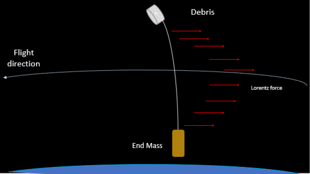
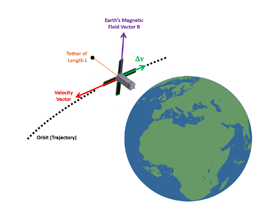
Figure 4 above shows the principle of an electrodynamic tether solution for removing orbital debris. The tether was deployed and is shown orbiting around the Earth with an end mass. Current runs through the tether, working along with the geomagnetic field of the planet. The bare side of the tether attaches itself to the orbital debris using a hooker or connecter. After capture, the end mass allows the system to rotate and release the tether and orbital debris. The system then deorbit itself and burns up into the atmosphere, removing the debris overall. This concept is used in the KITE experiment from JAXA. Previous studies show that debris objects that should be removed from crowded orbits can re-enter the Earth’s atmosphere within one year. Having a system with at least a 10-km tether on a host satellite should be able to eliminate that [8].
If a space craft can deploy a long cable of length L cable of carrying an electric current I, then as it orbits the interaction between Earth’s magnetic field B and the cable will generate a force given by:
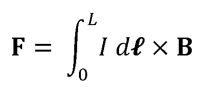
Figure below shows a simplistic diagram of the relationship between the orientation of the cable and the force F that would be generated by a deployed cable in orbit. The result force will be orthogonal to both the cable and Earth’s magnetic field. As such, it acts in the direction opposite to the velocity vector of the object that deployed the cable. Thus, it is effectively delivering negative Δv to the space craft and causing its orbit to decay.
Below are reported the Advantages and Disadvantages of Electrodynamic Tether:
Advantages:
- Being EDT simple and passive device, it can be easily installed on many small satellites
- It can be used not only to de-orbit a small spacecraft but also for increasing their orbital altitude as well.
- it can be used to generate electrical power which can be used to charge batteries thereby supplementing the function of solar panels. Unlike solar panels, however, they can generate power regardless if the sun is in view or not
Disadvantages:
- Risk of impact with orbital debris
- It only works on objects that have it designed and built into them. This means that it cannot be used on random space debris unless there is a way to attach a compact and self-contained EDT system to the debris on orbit.
- Mechanism used for reeling out the cable can be difficult to design, they can be made to be rather compact and fit in most small space vehicles
Deployable Nets
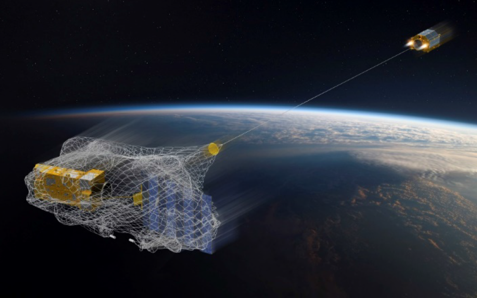
Deployable nets are perhaps the easiest to understand technology that has been proposed for orbital debris removal. The idea is to deploy something akin to a fisher’s net called a tether-net from a chaser spacecraft (still connected to the net) in the proximity of orbital debris. The tether-net is deployed ahead of the debris to be removed. The debris slowly drifts into and gets tangled by the tether net. Then the chaser spacecraft fires thrusters to change the orbit of itself and of the debris in the net such that they will reenter Earth’s atmosphere and burn.
While conceptually simple, the design of the nets themselves and the debris removal operation using them can be complex. For example, proposed nets are a collection of elastic rods connected. The rods can be connected by knots, or elastic joints. As a deformable body, the elastic rod can bend and form around the target to secure and capture it. Most nets considered for orbital debris removal are Cosserat nets. Cosserat nets consist of a network of elastic rods and elastic joints that link together to create a deformable body [9].
Furthermore, nets need to have a closing mechanism to allow satellites to release net once debris is captured. These can also be complex to design and operate in space.
The deployable net solution can be explained using the practices of fishing. Fishermen locate the fish and eject a net from a safe distance. The net comes with a closing mechanism to secure capture and reel the net back up to the surface.
Figure 5 below shows the similar concept occurring with the deployable net solution in space. The net is transported into space on a host satellite in a container. Once the satellite is at desired altitude, the net is deployed and captures targeted debris using its closing mechanism. The closing mechanism would be the end points on the corners of the net to ensure proper capture. The satellite will then travel to a lower altitude and cut the net with the attached debris for it to de-orbit and burn up in the atmosphere.
Below are reported the Advantages and Disadvantages of Deployable Nets:
Advantages:
- Unlike the other solutions, deployable nets can capture a large group of debris at one time.
- Due to previous advantage, it is oneof the more cost-efficient solutions.
Disadvantages:
- The Net needs proper spatial awareness for proper capture. Without proper attitude and control practices from the host satellite, this would be difficult for the net to capture the debris.
- Risk of possible stuck onto the host satellite. This can cause issues in its operation, thus failing the mission
References:
[1] J. Campell, “Project Orion: Orbital Debris Removal Using Ground Based Sensors and Lasers,” National Aeronautics and Space Administration, MSFC, Alabama, 1996.
[2] L. Zhou, X.-Y. Li, W.-J. Zhu, J.-X. Wang and C.-J. Tang, “The effects of pulse duration on ablation ressure driven by laser radiation,” Journal of Applied Physics, vol. 117, no. 12, 31 March 2015.
[3] K.-C. Lee, T. Taira, G. Mo Koo, J. Young Lee and J. J. Yoh, “Ignition characteristics of laser-ablated aluminum at shock pressures up to 2 GPa,” Journal of Applied Physics, vol. 115, no. 1, 3 January 2014.
[4] M. Sandoval, “Space Tethers,” University of Colorado, Boulder, 2007.
[5] M. Dobrowolny and N. Stone, “A technical overview of TSS-1: The first Tethered-Satellite system mission,” Il Nuovo Cimento, vol. C, no. 17, pp. 1-12, 1994.
[6] “Plasma turbulence enhanced current collection: Results from the plasma motor generator electrodynamic tether flight,” Journal of Geophysical Research: Space Physics, vol. 100, no. A2, 1 February 1995.
[7] J. Ballance and L. Johnson, “Propulsive Small Expendable Deployer System (ProSEDS),” AIP Conference Proceedings, vol. 552, no. 1, 4 April 2001.
[8] The Aerospace Corporation, “Danger: Orbital Debris,” 4 May 2018.
[9] J. Spillmann and M. Teschner, “Cosserat Nets,” IEEE Transactions on Visualization and Computer Graphics, vol. 15, no. 2, pp. 325-338, March 2009.