This article deals with strength criteria for composite materials supported by FEM analysis Some numerical example is shown by using MSC Nastran/Patran software. The most important criteria are explained and then a comparison by numerical results is performed.
The strength criteria of composite materials are commonly:
1 Max.Stress/Strain
2 Tsai-Hill Criteria
3 Hoffman Criteria
4 Tsai-Wu Criteria
In order to perform a numerical comparison amongst these criteria a simple model has been created by MSC Nastran/Patran.
Remind:
Definition of composite material: A composite material is a material made from two or more constituent materials with significantly different physical or chemical properties that, when combined, produce a material with different characteristics from the individual components. In the Aerospace industry is used usually the CFRP (Carbon Fiber Reinforced Plastic) that is an extremely strong and light fiber-reinforced plastic which contains carbon fibers. The binding polymer (Matrix) is often a thermoset resin such as epoxy, but other thermoset or thermoplastic polymers, such as polyester, vinyl ester, or nylon, are sometimes used.
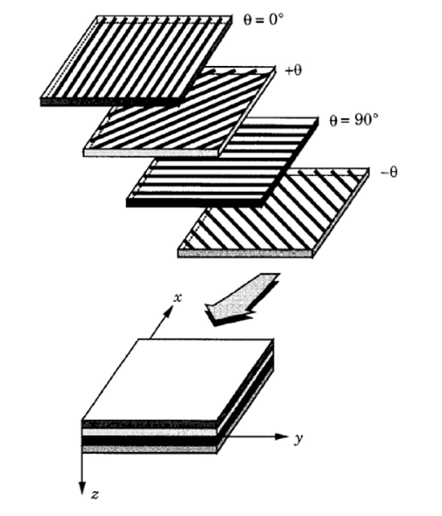
Definition of Lamina: In materials science, a composite laminate is an assembly of layers of fibrous composite materials which can be joined to provide required engineering properties, including in-plane stiffness, bending stiffness, strength, and coefficient of thermal expansion. A laminate is a stack of individual plies having a set of ply orientations (commonly 0°, 45°, 90°).
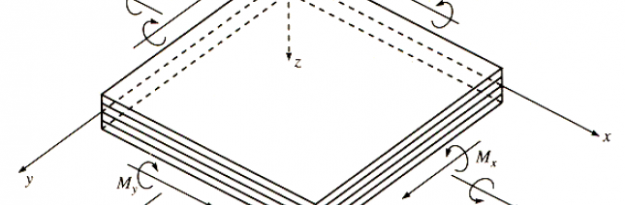
A simple model is used; it is made up by 3 plies with orthotropic properties with the goal to compare the criteria valid for the composite materials. The model is a rectangular plate loaded by an axial distributed load along Y-axis of coordinate system.


1 Max.Stress/Strain Criteria
This is a “not interactive” criteria. Indeed, every single stress or/and strain is separately compared with an allowable value (X- Y- XY- directions). This criterion is not conservative because it doesn’t take into account the interaction amongst the stress/strain components.
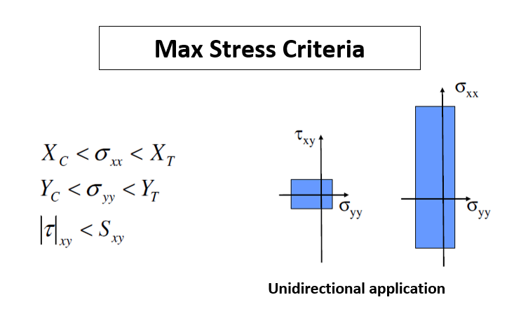
XT, XC, YT, YC, and SXY are the maximum stress allowable
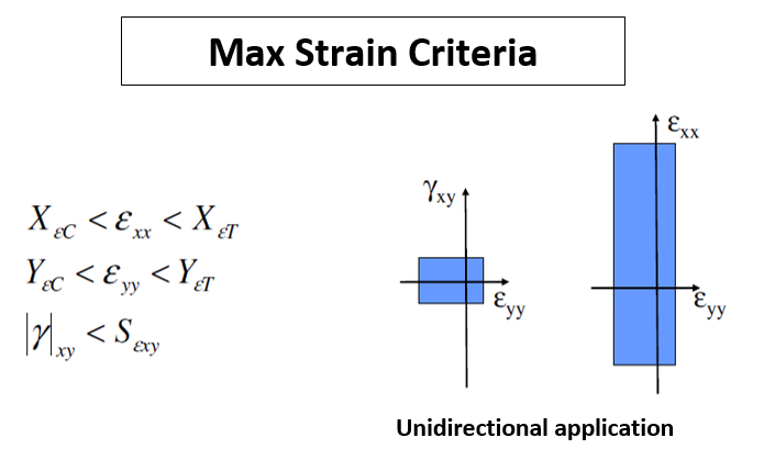
XεT, XεC, YεT, YεC, and SεXY are the maximum strain allowable

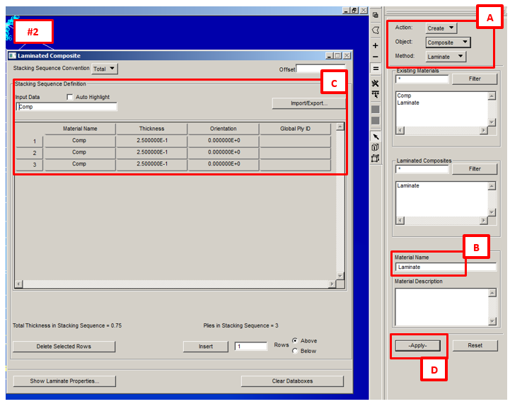
Sequence to create Laminate in Patran:
1) Material: Under Material’s menu, create the material “Comp“ with parameters indicated in the image below:

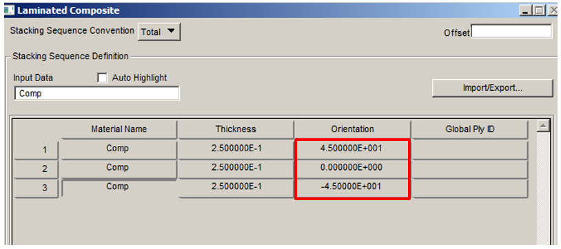
2) Under Material’s menu, create the “Laminate” according the image below:
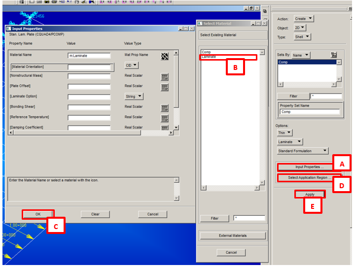
3) Under Properties menu, create the “Comp” property according the image below
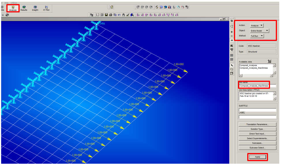
4) Then create the BDF text file for the next run with Natran, see below for the selection under Patran (leave SOL101 under “Solution type…”).
Here find the BDF built up as descripted above:
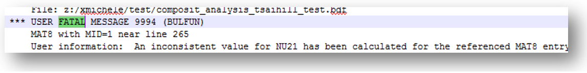
Note: if you got a fatal for the Nastran run like that one shown below, probably you should to erase the NU21 in the MAT8 card.
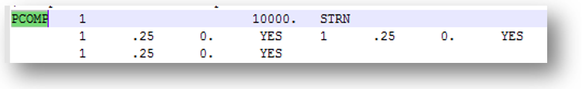
In the BDF file above, is printed out all the Nastran code. This bdf then is submitted to Nastran solver to get the results (in this case a XDB to be used by Patran for the post-process). In the BDF above, the “PCOMP” defines the lay-up of the laminate defined in Patran, below is reported the related Nastran card:
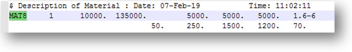
A MAT8 card is created as well in the BDF, and is reported below:
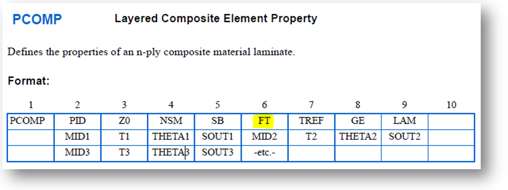
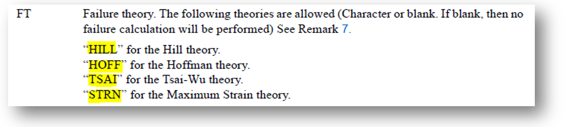
Useful exercise is to study by the Nastran-Quick Reference Guide (https://simcompanion.mscsoftware.com) the PCOMP card format (reported below). Highlighted in yellow the field related to failure criteria.
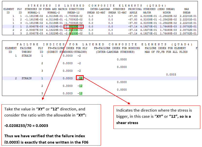
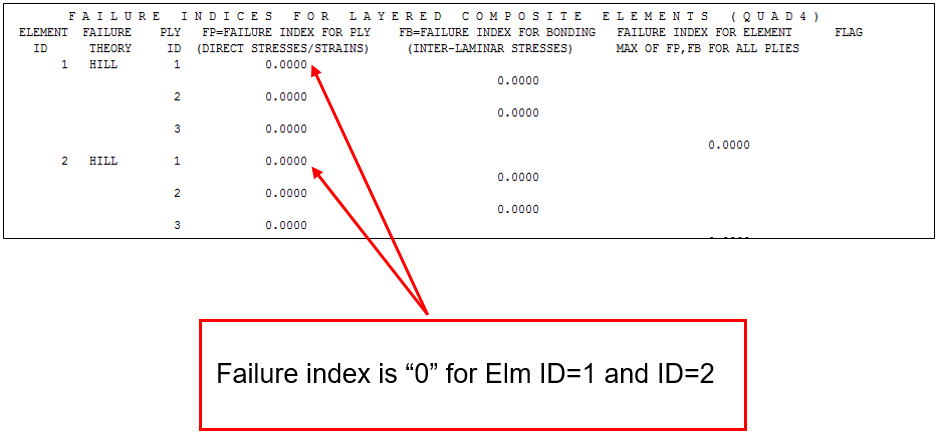
A F06 file is created as result of Nastran run. In this file are printed out the Failure Index. The Failure index indicates if the rupture limit is reached for each single lamina (in this case we have 3 plies) and for the matrix that bonds the fibers together. If the index is lower than 1, then the structure is not critical, on the contrary if is bigger than 1 there is a failure.

The same procedure for the element ID=2 to verify the failure index:
2 Tsai-Hill Criteria
This criterion is a quadratic or energetic criteria, also so-called “interactive” criteria. It is similar to Von Mises criteria used for isotropic material. This criterion is a 2D criteria (XY plane), based on the hypothesis that the material is isotropic in the transversal direction (strength in Z-direction equal to Y-direction).
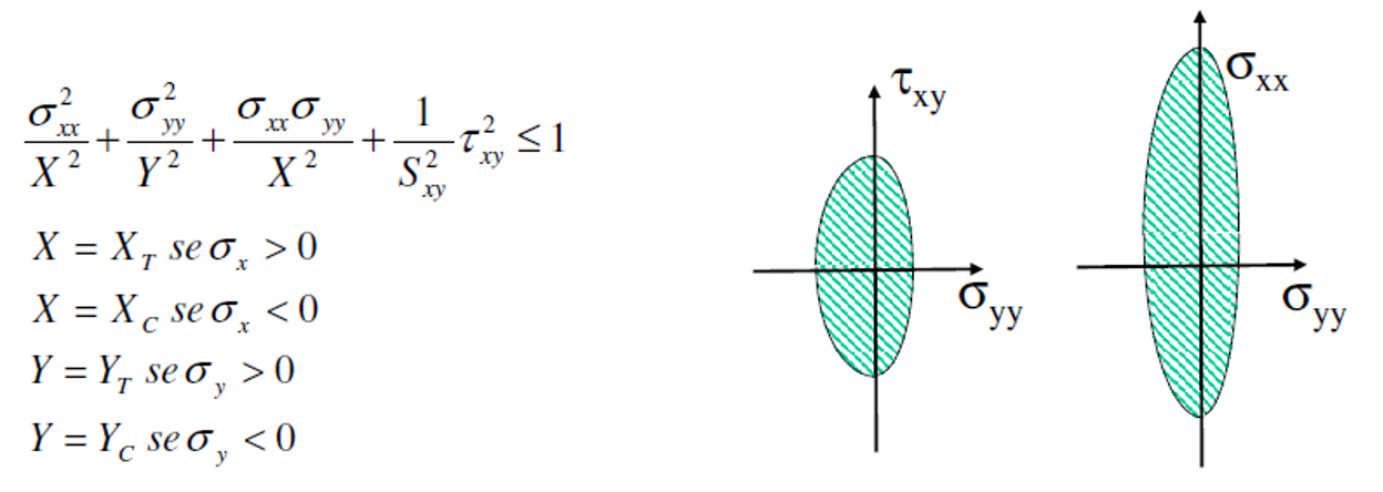
XT, XC, YT, YC, and SXY are the maximum stress allowables
Also in this case for our numerical verification is used the same FEM, and same boundary conditions used above for the Max Stress/Strain criteria. Except obviously for the criteria definition selected for the material (see below).

Likewise done for the Max Stress/Strain criteria, we take the Element ID=1 and ID=2, in order to compare the index values with those ones of Max Stress Criteria for the same loading.
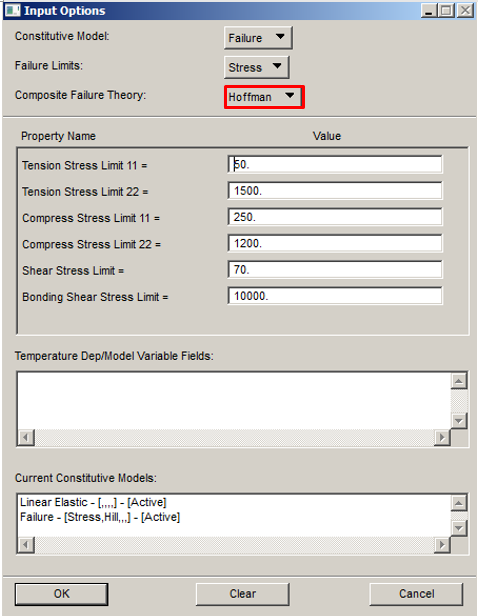
3 Hoffman Criteria
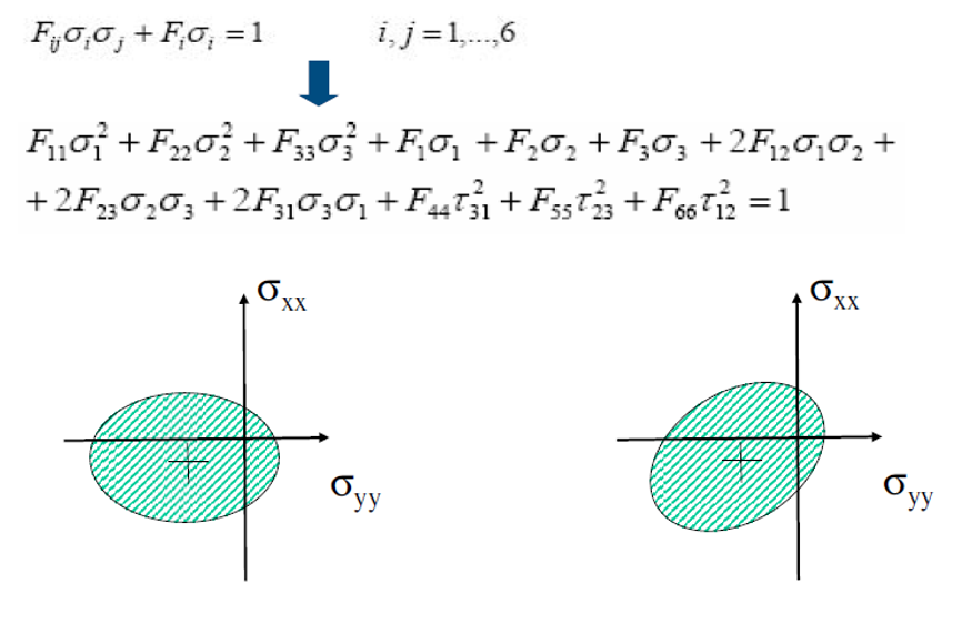
This criterion is a quadratic or energetic criteria, also so-called “interactive” criteria. It is similar to Von Mises criteria used for isotropic material. With respect the Tsai-Hill criteria this criterion has a better correlation with the test’s results. This criterion works well with materials loaded in one direction, but have some problem with biaxial load conditions. Below the formulation for this criteria:
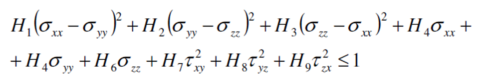
The 9 parameters are determined by 9 experimental tests: XT, XC, YT, YC, SXY, SYZ, SZY.


In this case, setting in Patran for the material is:
4 Tsai-Wu Criteria
This criterion is a quadratic or energetic criteria, also so-called “interactive” criteria. This criterion is the most complete. Its parameters can be easily expressed in a reference systems different with respect the “Lamina” system. Below the formulation for this criteria:
The 9 parameters could be determined by 9 experimental tests: XT, XC, YT, YC, SXY, SYZ, SZY.
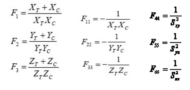
To determine the coupled factors (F12, F23, F31), biaxial traction tests are needed. However often these parameters are set to zero because the results present good correlations with experimental tests.
Setting in Patran for the material in this case:


Conclusion
In the table below are reported the failure indexes for each criteria and for 2 load conditions:
1st: total load of 21 N, 1N for each node ; 2nd: total load of 21*104 N, 103 N for each node.
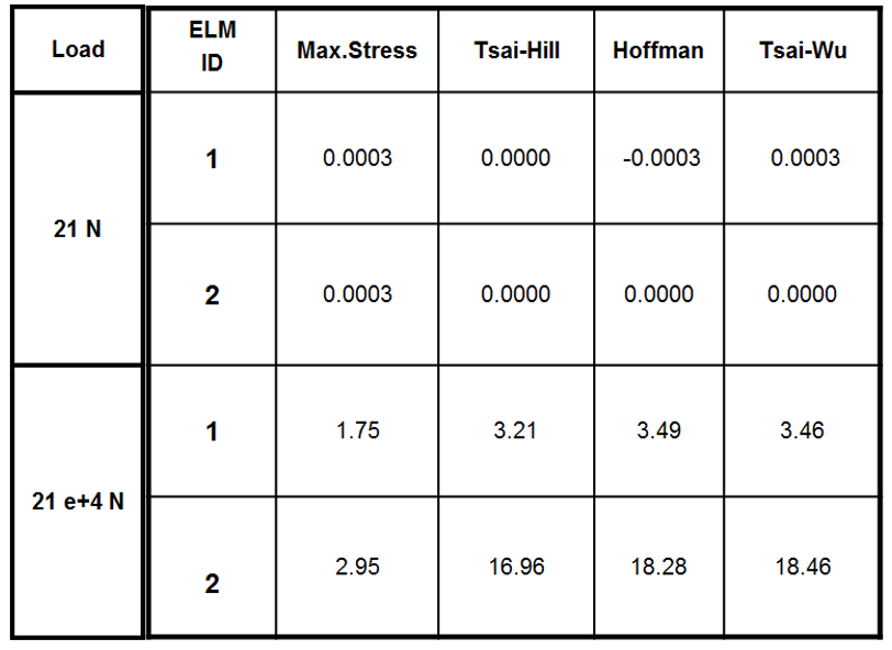
The Hoffman and Tsai-Wu criteria give similar failure indexes, for high and low loads. For high critical loads, Hoffman/Tsai-Wu give bigger failure indexes than Max Stress and Tsai-Hill, therefore are more conservative.
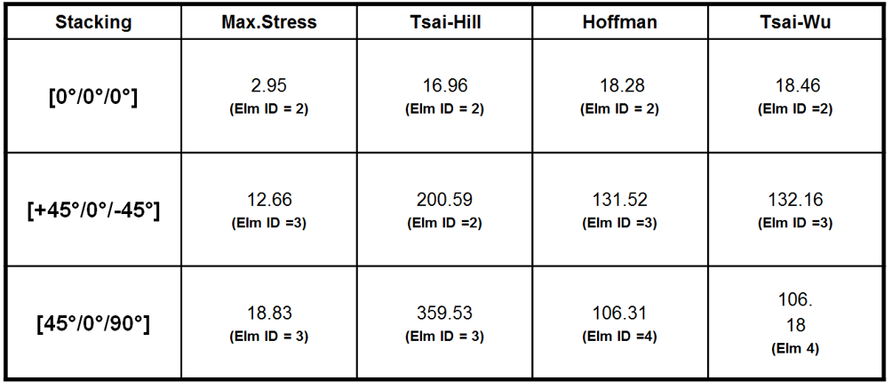
A further checks have been performed by considering a different orientation of the plies: [+45°/0°/-45°] ; [45°/0°/90°]. For the stacking [0°/0°/0°], Hoffman and Tsai-Wu give higher failure indexes, therefore in this case are more conservative.
For the stacking [+45°/90°/-45°] and [45°/0°/90°] instead, Tsai-Hill gives higher failure indexes, therefore in this case is the most conservative.
Here all the FEM models for each criteria:
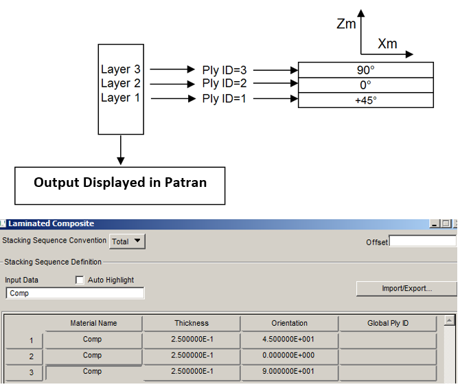
The stacking sequence in Patran is structured in order to the Ply ID=1 is that one with the most negative value of Zm-axis (material system), hence the stacking has sequence from the bottom to the top according the direction of Zm-axis.
[smartslider3 slider=”2″]