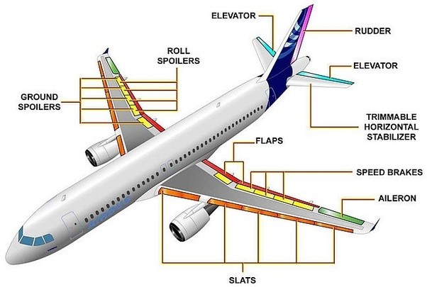
Aircraft flight control surfaces are aerodynamic devices allowing a pilot to adjust and control the aircraft’s flight attitude. This article describes the control surfaces used on a fixed-wing aircraft of conventional design. Other fixed-wing aircraft configurations may use different control surfaces but the basic principles remain. The Wright brothers are credited with developing the first practical control surfaces. It is a main part of their patent on flying.
1 – Main control surfaces
The main control surfaces of a fixed-wing aircraft are attached to the airframe on hinges or tracks so they may move and thus deflect the air stream passing over them. This redirection of the air stream generates an unbalanced force to rotate the plane about the associated axis.
1.1 Ailerons
Ailerons are mounted on the trailing edge of each wing near the wingtips and move in opposite directions. When the pilot moves the stick left, or turns the wheel counter-clockwise, the left aileron goes up and the right aileron goes down. A raised aileron reduces lift on that wing and a lowered one increases lift, so moving the stick left causes the left wing to drop and the right wing to rise. This causes the aircraft to roll to the left and begin to turn to the left. Centering the stick returns the ailerons to neutral maintaining the bank angle. The aircraft will continue to turn until opposite aileron motion returns the bank angle to zero to fly straight. The ailerons primarily control roll. Whenever lift is increased, induced drag is also increased. When the stick is moved left to roll the aircraft to the left, the right aileron is lowered which increases lift on the right wing and therefore increases induced drag on the right wing. Using ailerons causes adverse yaw, meaning the nose of the aircraft yaws in a direction opposite to the aileron application. When moving the stick to the left to bank the wings, adverse yaw moves the nose of the aircraft to the right. Adverse yaw is more pronounced for light aircraft with long wings, such as gliders. It is counteracted by the pilot with the rudder. Differential ailerons are ailerons which have been rigged such that the downgoing aileron deflects less than the upward-moving one, reducing adverse yaw.
1.2 Elevator
The elevator is a moveable part of the horizontal stabilizer, hinged to the back of the fixed part of the horizontal tail. The elevators move up and down together. When the pilot pulls the stick backward, the elevators go up. Pushing the stick forward causes the elevators to go down. Raised elevators push down on the tail and cause the nose to pitch up. This makes the wings fly at a higher angle of attack, which generates more lift and more drag. Centering the stick returns the elevators to neutral and stops the change of pitch. Some aircraft, such as an MD-80, use a servo tab within the elevator surface to aerodynamically move the main surface into position. The direction of travel of the control tab will thus be in a direction opposite to the main control surface. It is for this reason that an MD-80 tail looks like it has a ‘split’ elevator system.
In the canard arrangement, the elevators are hinged to the rear of a foreplane and move in the opposite sense, for example when the pilot pulls the stick back the elevators go down to increase the lift at the front and lift the nose up.
1.3 Rudder
The rudder is typically mounted on the trailing edge of the vertical stabilizer, part of the empennage. When the pilot pushes the left pedal, the rudder deflects left. Pushing the right pedal causes the rudder to deflect right. Deflecting the rudder right pushes the tail left and causes the nose to yaw to the right. Centering the rudder pedals returns the rudder to neutral and stops the yaw.
The rudder is a fundamental control surface which is typically controlled by pedals rather than at the stick. It is the primary means of controlling yaw—the rotation of an airplane about its vertical axis. The rudder may also be called upon to counter-act the adverse yaw produced by the roll-control surfaces.
If rudder is continuously applied in level flight the aircraft will yaw initially in the direction of the applied rudder – the primary effect of rudder. After a few seconds the aircraft will tend to bank in the direction of yaw.
This arises initially from the increased speed of the wing opposite to the direction of yaw and the reduced speed of the other wing. The faster wing generates more lift and so rises, while the other wing tends to go down because of generating less lift. Continued application of rudder sustains rolling tendency because the aircraft flying at an angle to the airflow – skidding towards the forward wing. When applying right rudder in an aircraft with dihedral the left hand wing will have increased angle of attack and the right hand wing will have decreased angle of attack which will result in a roll to the right. An aircraft with anhedral will show the opposite effect. This effect of the rudder is commonly used in model aircraft where if sufficient diheral or polyhedral is included in the wing design, primary roll control such as ailerons may be omitted altogether.
2 – Secondary control surfaces
2.1 Spoilers
On low drag aircraft such as sailplanes, spoilers are used to disrupt airflow over the wing and greatly reduce lift. This allows a glider pilot to lose altitude without gaining excessive airspeed. Spoilers are sometimes called “lift dumpers”. Spoilers that can be used asymmetrically are called spoilerons and can affect an aircraft’s roll.
2.2 Flaps
Flaps are mounted on the trailing edge on the inboard section of each wing (near the wing roots). They are deflected down to increase the effective curvature of the wing. Flaps raise the maximum lift coefficient of the aircraft and therefore reduce its stalling speed.They are used during low speed, high angle of attack flight including take-off and descent for landing. Some aircraft are equipped with “flaperons”, which are more commonly called “inboard ailerons”. These devices function primarily as ailerons, but on some aircraft, will “droop” when the flaps are deployed, thus acting as both a flap and a roll-control inboard aileron.
2.3 Slats
Slats, also known as leading edge devices, are extensions to the front of a wing for lift augmentation, and are intended to reduce the stalling speed by altering the airflow over the wing. Slats may be fixed or retractable – fixed slats give excellent slow speed and STOL capabilities, but compromise higher speed performance. Retractable slats, as seen on most airliners, provide reduced stalling speed for take-off and landing, but are retracted for cruising.
2.4 Air brakes
Air brakes are used to increase drag. Spoilers might act as air brakes, but are not pure air brakes as they also function as lift-dumpers or in some cases as roll control surfaces. Air brakes are usually surfaces that deflect outwards from the fuselage (in most cases symmetrically on opposing sides) into the airstream in order to increase form-drag. As they are in most cases located elsewhere on the aircraft, they do not directly affect the lift generated by the wing. Their purpose is to slow down the aircraft. They are particularly useful when a high rate of descent is required. They are common on high performance military aircraft as well as civilian aircraft, especially those lacking reverse thrust capability.
2.5 Tabs
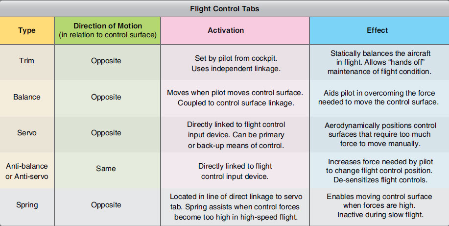
The force of the air against a control surface during the high speed of flight can make it difficult to move and hold that control surface in the deflected position. A control surface might also be too sensitive for similar reasons. Several different tabs are used to aid with these types of problems. The table in Figure below summarizes the various tabs and their uses.
While in flight, it is desirable for the pilot to be able to take his or her hands and feet off of the controls and have the aircraft maintain its flight condition. Trims tabs are designed to allow this. Most trim tabs are small movable surfaces located on the trailing edge of a primary flight control surface. A small movement of the tab in the direction opposite of the direction the flight control surface is deflected, causing air to strike the tab, in turn producing a force that aids in maintaining the flight control surface in the desired position. Through linkage set from the cockpit, the tab can be positioned so that it is actually holding the control surface in position rather than the pilot. Therefore, elevator tabs are used to maintain the speed of the aircraft since they assist in maintaining the selected pitch. Rudder tabs can be set to hold yaw in check and maintain heading. Aileron tabs can help keep the wings level.
Occasionally, a simple light aircraft may have a stationary metal plate attached to the trailing edge of a primary flight control, usually the rudder. This is also a trim tab as shown in Figure below. It can be bent slightly on the ground to trim the aircraft in flight to a hands-off condition when flying straight and level. The correct amount of bend can be determined only by flying the aircraft after an adjustment. Note that a small amount of bending is usually sufficient.
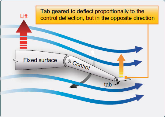
The aerodynamic phenomenon of moving a trim tab in one direction to cause the control surface to experience a force moving in the opposite direction is exactly what occurs with the use of balance tabs. (Figure below) Often, it is difficult to move a primary control surface due to its surface area and the speed of the air rushing over it. Deflecting a balance tab hinged at the trailing edge of the control surface in the opposite direction of the desired control surface movement causes a force to position the surface in the proper direction with reduced force to do so. Balance tabs are usually linked directly to the control surface linkage so that they move automatically when there is an input for control surface movement. They also can double as trim tabs, if adjustable in the flight deck.
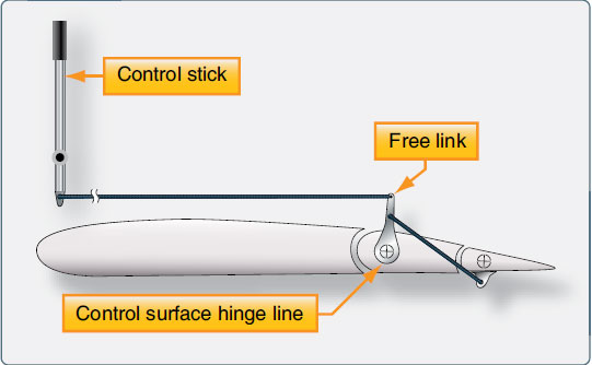
A servo tab is similar to a balance tab in location and effect, but it is designed to operate the primary flight control surface, not just reduce the force needed to do so. It is usually used as a means to back up the primary control of the flight control surfaces. (Figure below)
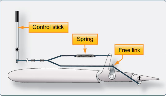
On heavy aircraft, large control surfaces require too much force to be moved manually and are usually deflected out of the neutral position by hydraulic actuators. These power control units are signaled via a system of hydraulic valves connected to the yoke and rudder pedals. On fly-by-wire aircraft, the hydraulic actuators that move the flight control surfaces are signaled by electric input. In the case of hydraulic system failure(s), manual linkage to a servo tab can be used to deflect it. This, in turn, provides an aerodynamic force that moves the primary control surface. A control surface may require excessive force to move only in the final stages of travel. When this is the case, a spring tab can be used. This is essentially a servo tab that does not activate until an effort is made to move the control surface beyond a certain point. When reached, a spring in line of the control linkage aids in moving the control surface through the remainder of its travel. (Figure below)
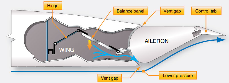
Figure below shows another way of assisting the movement of an aileron on a large aircraft. It is called an aileron balance panel. Not visible when approaching the aircraft, it is positioned in the linkage that hinges the aileron to the wing.
Balance panels have been constructed typically of aluminum skin-covered frame assemblies or aluminum honeycomb structures. The trailing edge of the wing just forward of the leading edge of the aileron is sealed to allow controlled airflow in and out of the hinge area where the balance panel is located.
When the aileron is moved from the neutral position, differential pressure builds up on one side of the balance panel. This differential pressure acts on the balance panel in a direction that assists the aileron movement. For slight movements, deflecting the control tab at the trailing edge of the aileron is easy enough to not require significant assistance from the balance tab. (Moving the control tab moves the ailerons as desired.) But, as greater deflection is requested, the force resisting control tab and aileron movement becomes greater and augmentation from the balance tab is needed. The seals and mounting geometry allow the differential pressure of airflow on the balance panel to increase as deflection of the ailerons is increased. This makes the resistance felt when moving the aileron controls relatively constant.
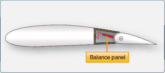
The trailing edge of the wing just forward of the leading edge of the aileron is sealed to allow controlled airflow in and out of the hinge area where the balance panel is located.
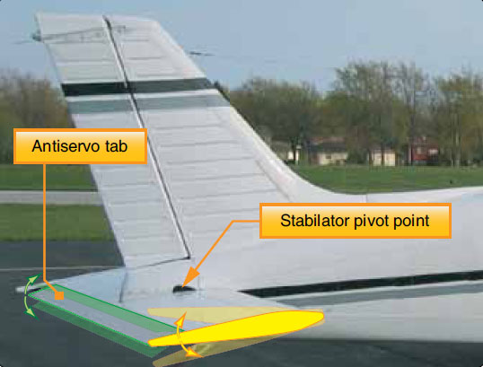
Antiservo tabs, as the name suggests, are like servo tabs but move in the same direction as the primary control surface. On some aircraft, especially those with a movable horizontal stabilizer, the input to the control surface can be too sensitive. An antiservo tab tied through the control linkage creates an aerodynamic force that increases the effort needed to move the control surface. This makes flying the aircraft more stable for the pilot. Figure below shows an antiservo tab in the near neutral position. Deflected in the same direction as the desired stabilator movement, it increases the required control surface input.
2.6 Other Wing Features
There may be other structures visible on the wings of an aircraft that contribute to performance. Winglets, vortex generators, stall fences, and gap seals are all common wing features.
A winglet is an obvious vertical upturn of the wing’s tip resembling a vertical stabilizer. It is an aerodynamic device designed to reduce the drag created by wing tip vortices in flight. Usually made from aluminum or composite materials, winglets can be designed to optimize performance at a desired speed. (Figure below)
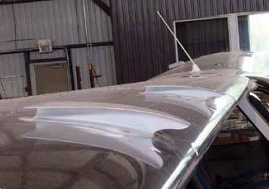
Vortex generators are small airfoil sections usually attached to the upper surface of a wing (Figure below). They are designed to promote positive laminar airflow over the wing and control surfaces. Usually made of aluminum and installed in a spanwise line or lines, the vortices created by these devices swirl downward assisting maintenance of the boundary layer of air flowing over the wing (Figure below)
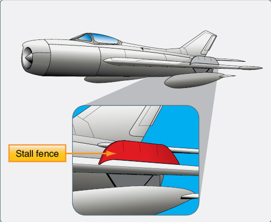
A chordwise barrier on the upper surface of the wing, called a stall fence, is used to halt the spanwise flow of air. During low speed flight, this can maintain proper chordwise airflow reducing the tendency for the wing to stall. Usually made of aluminum, the fence is a fixed structure most common on swept wings, which have a natural spanwise tending boundary air flow. (Figure below)
Often, a gap can exist between the stationary trailing edge of a wing or stabilizer and the movable control surface(s). At high angles of attack, high pressure air from the lower wing surface can be disrupted at this gap. The result can be turbulent airflow, which increases drag. There is also a tendency for some lower wing boundary air to enter
the gap and disrupt the upper wing surface airflow, which in turn reduces lift and control surface responsiveness. The use of gap seals is common to promote smooth airflow in these gap areas. Gap seals can be made of a wide variety of materials ranging from aluminum and impregnated fabric to foam and plastic. Figure below shows some gap seals installed on various aircraft.
Turning the aircraft
Unlike turning a boat, changing the direction of an aircraft normally must be done with the ailerons rather than the rudder. The rudder turns (yaws) the aircraft but has little effect on its direction of travel. With aircraft, the change in direction is caused by the horizontal component of lift, acting on the wings. The pilot tilts the lift force, which is perpendicular to the wings, in the direction of the intended turn by rolling the aircraft into the turn. As the bank angle is increased, the lifting force can be split into two components: one acting vertically and one acting horizontally.
If the total lift is kept constant, the vertical component of lift will decrease. As the weight of the aircraft is unchanged, this would result in the aircraft descending if not countered. To maintain level flight requires increased positive (up) elevator to increase the angle of attack, increase the total lift generated and keep the vertical component of lift equal with the weight of the aircraft. This cannot continue indefinitely. The total load factor required to maintain level flight is directly related to the bank angle. This means that for a given airspeed, level flight can only be maintained up to a certain given angle of bank. Beyond this angle of bank, the aircraft will suffer an accelerated stall if the pilot attempts to generate enough lift to maintain level flight.
