The fuselage frame is a principal structural element of the aircraft shell structure, it is important for the following reasons:
- ensuring a certain shape to the fuselage, establishing an aerodynamic requirements that must be met. Frames used purely to have a certain shape are usually located in the tail of the fuselage;
- absorbing the loads, for example that imposed on the fuselage structure in the landing or those introduced in the fuselage from the wings. It transmits these loads to the skin;
- It works as stiffening elements for the skin. Indeed for the presence of the stringers and the frames the skin is divided into many panels riveted precisely on the same stringers and frames that act like a constraints in order to improve the post-buckling behaviour.
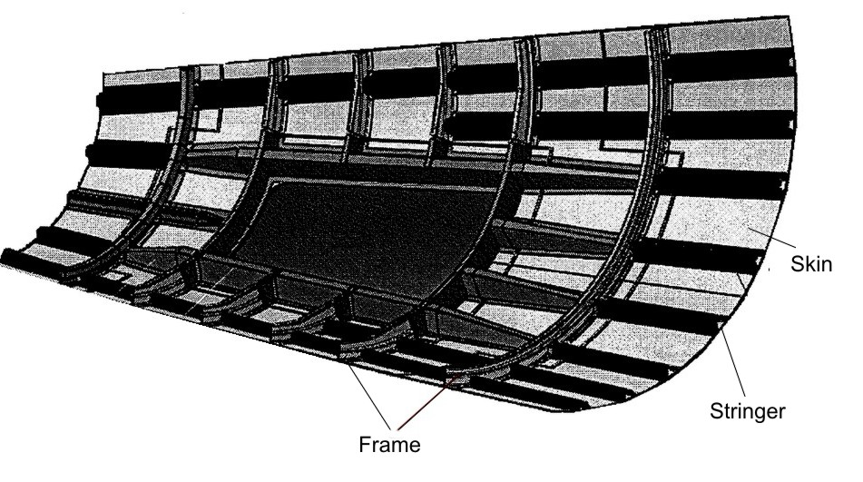
Fig1 – typical side shell of aircraft fuselage
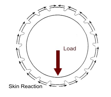
Fig 2 – Load and skin reaction
The frames may be considered like free beams subject to a balanced load constituted by the external forces that are applied on it and balanced by the shear fluxes of the skin. which are the reaction to the same external loads that are transmitted through the frame. in the following figure a scheme is shown.
Analysis Procedure
- Data
In this article we consider a circular and symetric closed Frame with a symmetric load applied. We can consider just the half of the external load applied R/2. The Frame is built up by 17 stringers made in aluminium and their positions are expressed by percentage of the height T of the fuselage. We also assume that the Frame has constant thickness and straight and constant section with the following values:
- t= 0 mm
- s= 2 mm
- L1=62 mm
- L2=32 mm
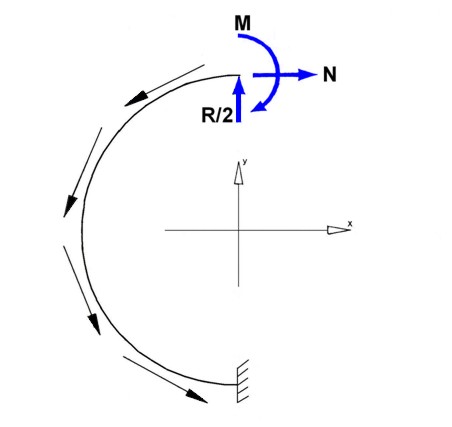
Fig 3 – Frame Loads
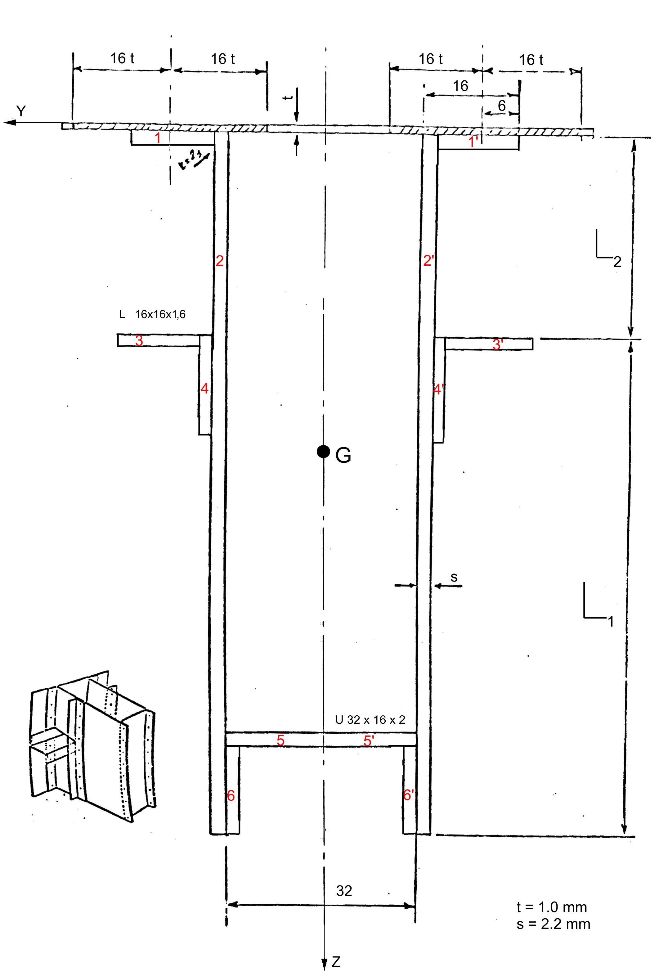
Fig 4 – Frame section
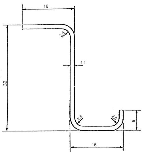
Fig 5 – Stringer section
We assume that the Lift of each wing (with L / 2) is applied at a distance along Y of 50 mm from the skin of the fuselage. and along Z of 180 mm from the base of the fuselage (so after the current 13 in our case).
Loads applied:
M= 145000000 Nmm – Bending Moment
R = 40000 N (we use L/2 for the symmetry)
- Calculation
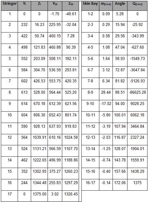
The first step is to make the drawing of the outline of the fuselage following the instructions in drawing plans for the Frame (see Figure 6; L=615. S=627. I=748). Due to the symmetry of the fuselage with respect to z. it is shown only one half. The position of each stringers and their result are shown in the table 1 and the position figures below .
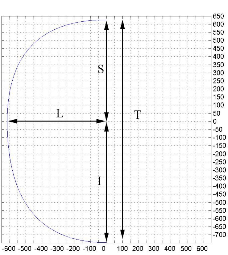
Fig 6 – Frame – Geometry data

Fig 7 – Stringer position
By the Fig 5 we can calculate the stringer section area. The area of an annulus for the sectors areas : 3* [π/4*(R2 -r2)] = 15.81 mm2 . Thus we have: A = (48.4 * t) – 15.81 = 69.05 mm2 . The hypotesis that we do for the neutral axis is that it is located between the stringer 8 and 9; thus we have that:
– The stringer from 1 to 8 are compressed ;
– The stringer 9 to 17 are in tension.
We have to take into account that the collaborant length related to the stringers partially in tension and in compression, for this scope is necessary to find the exact neutral axis position. For the are in tension we take as collaborant length, 2 times the length from the middle of the skin bay to the stringer, instead for the stringer compressed the Von Karmann formula is used. This procedure is iterated, in each step is identified the skin part compressed and part in tension, and the position of center of gravity.
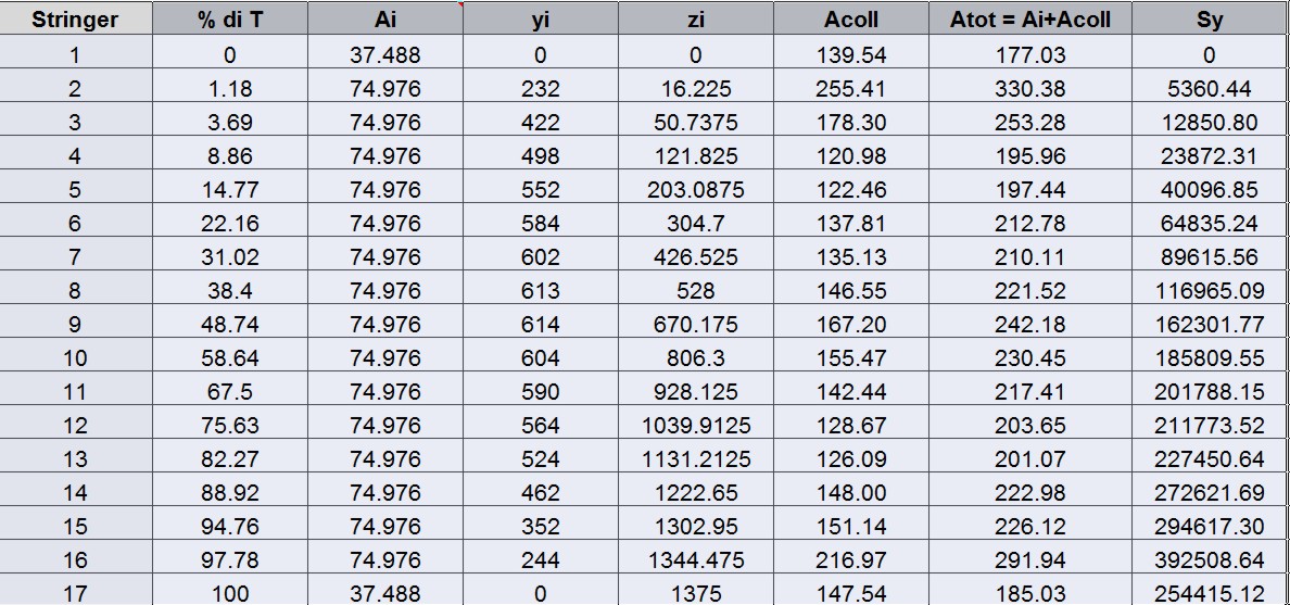
Table 1: Stringer – geometry
We now need to calculate the center of gravity and move the initial triad in G. Due to the symmetry of the entire Frame we can now write:
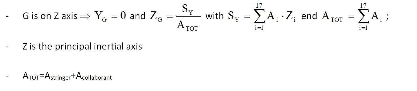
The collaborating areas are shown in Table. 2. The position of the center of gravity is:
ZG=SY / ATOT=2556882.68/3819.31=669.46
Considering as reference the center of gravity all the geometric quantities are calculated and shown below in the table.
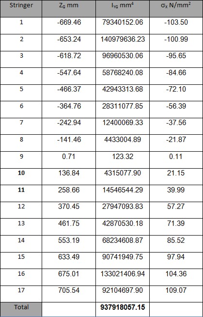
Table 2
Due to the simmetry of the reference system used the IXY is equal to zero, thus only IYGi=ATOT* zGi (IYG = ∑ IYGi) has to be calculated. Moreover since it is simalar to a beam bending (the force is applied along the barycentric symmetrcaly) for the Navier formula we have:
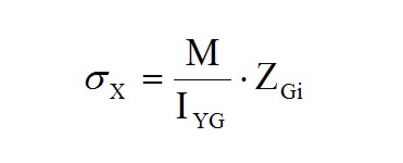
By the results obtained we observe that the neutral axis is between the stringer 8 and 9 (changing of the sign of σx); the Stringers from 1 to 8 are compressed and from 9 and 17 are in tension. The σx for each string is lower than to allowable (σyield = 220 N/mm2). Thus the stress is in the elastic range, therefore to calculate the “cooperating” length Ci we can use this expression (valid only for compressed stringer):
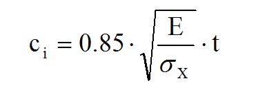
Afterwards an iteration has to be done by comparing the values in each of the collaborative areas, and it will be arrested when the difference between the values of two successive iterations does not exceed 1% of the individual values. The tab.3 shows the final values. The convergence is reached after five iterations. In this case the compression-tension area is between the stringer 10 and 11:
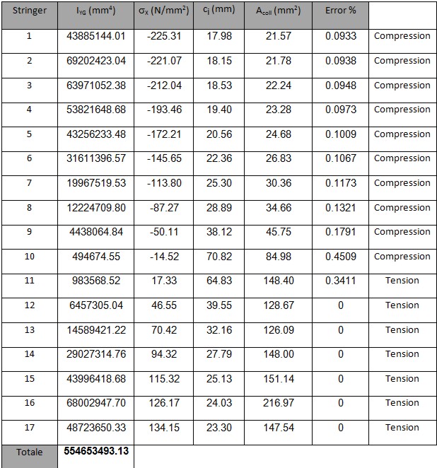
Tab3
while : ZG=861.84 mm. Now we can build up the structure with equivalent concentrated elements, and afterwards we can perform the calculation of the shear flow in the skin due to application of the T=40000 N. Exploiting the symmetry of the structure with respect to Z, now we can calculate the shear flows due to the force T applied along Z (assuming that the section is open) by this formula:

Tab 4
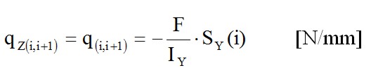
Since Iy is calculated considering only half structure. will be considered only half of T, thus T/2= 20000 N. The shear fluxes obtained by this allied T being shown in in table 5. By the shear fluxes is possible to calculate the shear ΔT(i.i+1) by this equation:
ΔT(i.i+1)= q(i.i+1)• l(i.i+1)
Assuming a flat skin between i and i+1:
![]()
As for the application of shear a straight line through i and i + 1 is taken. The values for the Shear are reported in table 5. Moreover It is also possible to check the equilibrium by calculating the vertical and horizontal components of ΔT ; the resultant of horizontal component is equal to nil due to the symmetry, while for the vertical ones the resultant is equal to T / 2.
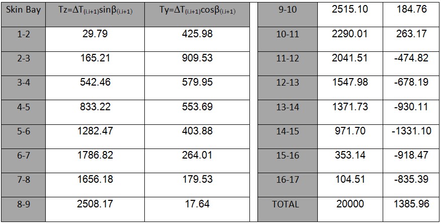
Tab 5
Solution if the hyperstatic variables
Due to closed frame this type of structure is “multi connected” with 3 hyperstatic variables: T, M, and N. To make it “mono connected” is sufficient to divide the strucuture in 2 symmetrical parts and study only one side.
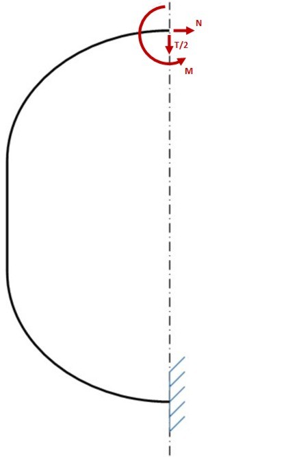
Once the structure has been separated, it is necessary to restore the previous state of equilibrium by applying the loads (T, N, M) that the right half would apply on the left side without the cutting. Moreover due to the geometric and loading symmetry with respect of axis Z, the shear T is zero on the Z axis. Consequently the structure has 2 hyperstatic variables instead of three.
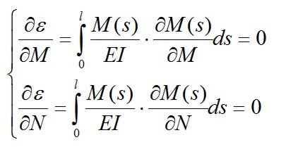
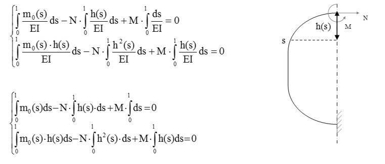
In this way the Frame is reduced to a curved beam with a fixed constrains on one end, and loaded with M and N and the other end, and loaded by a distributed load per unit length (shear flow previously calculated) and from a concentrated load: the half “lift” L / 2 directed vertically upwards. The verify of this structure can be conducted if you know the trend of the bending moment along the axis of the beam. For this purpose we use the theorem of “Menabrea” that provides us with two equations with M and N.
As per this principle, in a hyperstatic structure with several external Fi forces we subtract the n constraints to obtain an isostatic structure. With the hypothesis of rigid constraints and absence of strains, the deformation energy ε=ε(Xi.Fi) (i=1…n) related to Fi and its hyperstatic reactions Xi (N. T. M), has to be equal to a in certain value in order to that its partial derivatives with respect Xi have to be equal to zero.
![]()
![]()
since in the presence of bending moment, the strain energy associated with the deformation by bending moment is much higher than the normal and shear stress and T=0, thus we have:
with l as length of the axis of the beam. S is the curvilinear abscissa taken on the axis of the beam. The total moment is equal to this formula:
![]()
where m0 (s) is a part of M (s) due to the distributed load and concentrated load, N • h (s) is the moment due to N (the moment is positive if the lower fibers of the beam being in tension) and h (s) is the distance of the section (with s as abscissa) from the straight line of application of N. Putting this formula in the equation system, we obtain the following linear system of two equations with N and M as variables:
If you know exactly the equation of the curve axis, you can solve analytically the integrals. Since this curve is not known, we proceed numerically in the following manner: choose the axis of the beam a number of points taken in correspondence of the stringers, then those points are connected with straight lines; afterwards the broken line being assumed as the axis of the beam, and then tequations mentioned above are evaluated in these points. In Fig. 6. for example, is reported the case of 7-stringers.
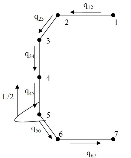
Fig6 – Example of discretization
The first step is the calculation of the discretizated trend mo(s)=m0(i, i+1):
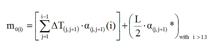
where α(i)(j.j+1) is the distance between the centroid of the beam section located in correspondence of the i-th stringer and the straight line passing through the two stringers j and j + 1, while α(i)(j.j+1)* it is the distance between the direction of L / 2 and the centers of gravity of the sections placed in correspondence of the stringers; this contribution is only from the thirteenth current, since the attack wing is placed after this location. Analytically such distances can be found by calculating the distance between the centroid of the beam section located in correspondence of the i-th stringer and the straight line that joins the two stringers in j and j + 1; the formula used is:

where:
– m(j.j+1) is the angular coefficient of the straight line joining the two closed stringers j, j + 1;
– (Yi; Zi) are coordinates of the generic centroid of the beam section located in correspondence of the i-th stringer
– Q(j.j+1) is the intersection of the generic straight line (the line by means has been discretized the Frame) with the z axis. The following tables contain the numerical values.
Tab 6
By the values of the function m0 at each center of gravity, we assume a linear path between two consecutive centroids, thus we obtain the diagram shown in Figure 8 and in tab 7.

Fig8
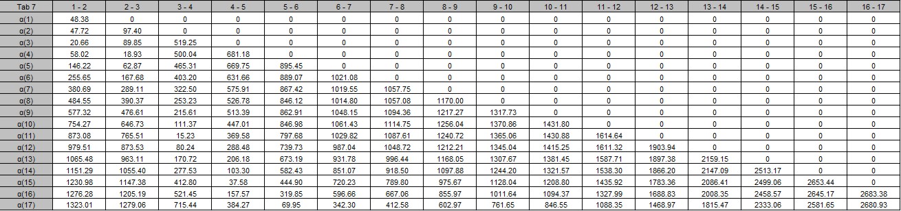
Tab 7
The integral is approximated by the area under the curve whom being calculated as the sum of the areas of each trapezoid subtended by the curve:
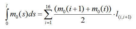
The results obtained by this formula are shown in the table below.
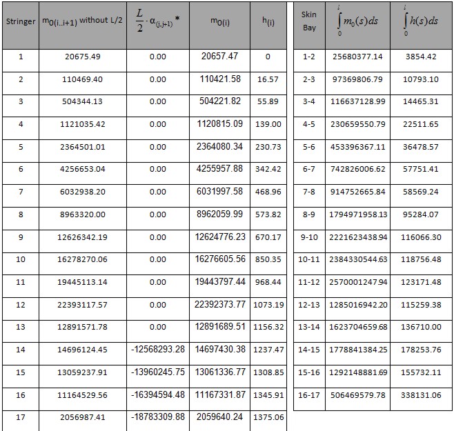
Tab 8
In the similar manner we calculate the other integrals (results in Tab 9):
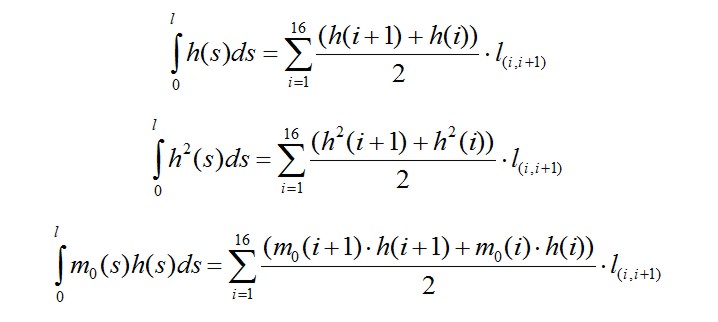
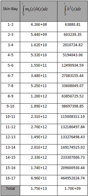
Tab 9
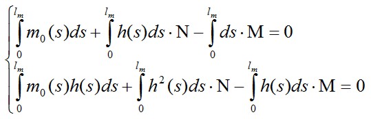
Once the integrals being calculated, we can solve the system of two equations above to calculate M and N. The system is rewritten as:
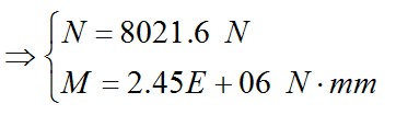
Now we can determine the total Moment i-th along the frame by the formula already mentioned above:
![]()
The numerical values are shown in table 10, while in Fig. 9 and Fig. 10 are shown respectively the values of N·h(i) and M(i).
Tab 10
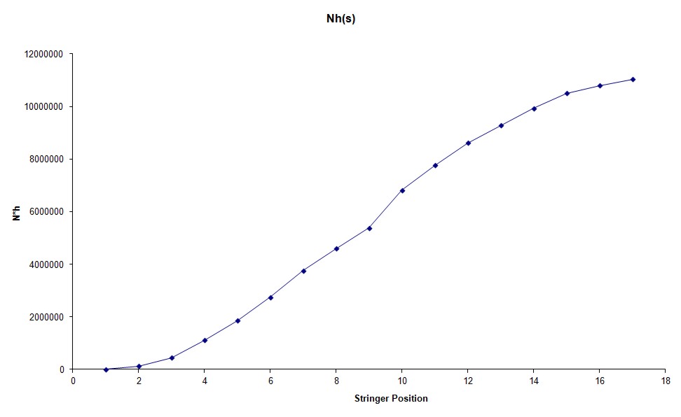
Fig 9
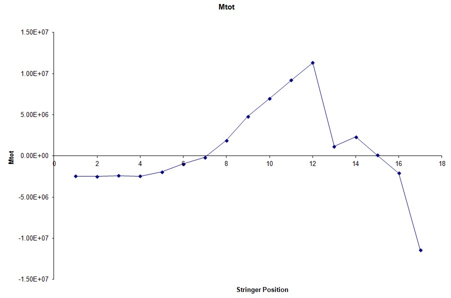
Fig 10
Strength Check
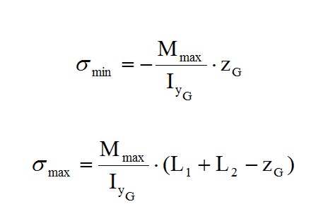
As is deductible from tab. 10 as well as from Fig. 10 the section more stressed is located in Stringer 17. therefore is performed a verification of resistance in this section of the Frame. which means to calculate the σmax and σmin on the external bounds with Max (Navier’s formula):
The inertia and the COG of the section (Fig.4) have to be calculated for this scope. the tab. 11 shows the values that we need for verification.
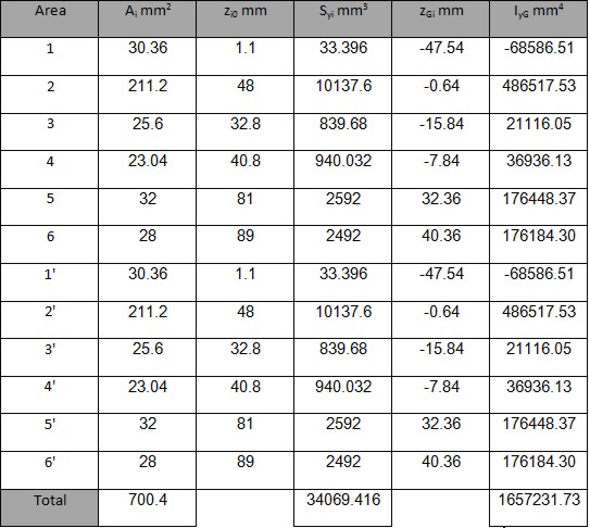
Tab 11
Thus we have:
![]()

Moreover we have to consider the σ due to the shear and normal component acting from the 13th Stringer:
To reach this aim we proceed with following steps:
- Take in to account of the orthogonal line to the stringer-plane
- Calculation of the angle between the skin part (i,i+1) with the line mentioned above
- Projection of ΔT(i,i+1) e N in this direction and in the tangent one
- Summation of all that being before of the 13th stringer
Thus we obtain the table below
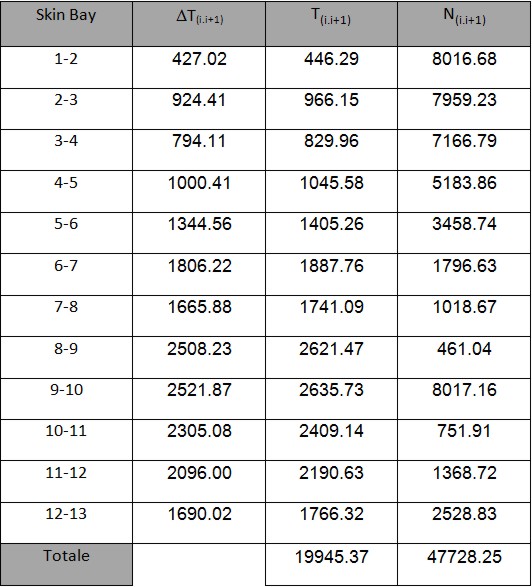
Tab 12
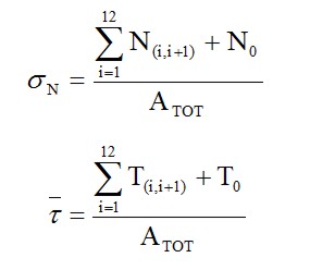
From this table we obtain:
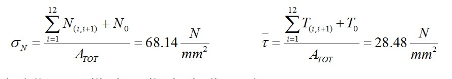
The check the strength we use Von Mises formula:
![]()
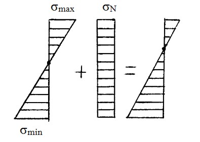
The σmin is calculated by the Navier formula (in this case we have a compression). The last step is to compare it with the allowable of the material. In this case the ultimate value is 490 N/mm2, thus this structure is able to safely sustain the load applied. You can download here the excel file with the entire frame analysis shown above.
engineering, aerospace, here
airspace
stress analysis
[smartslider3 slider=”2″]