Understanding hypersonic missile systems
Over the past weeks and months, ‘hypersonic missiles’ have again made headlines in global defence news. On 5 and 11 January, North Korea performed test flights of what it claims is a ‘hypersonic missile’. The announcement, the released pictures and the flight path suggest North Korea tested a rotational symmetric glide vehicle atop a rocket booster that performed pull-up and cross-range manoeuvres during its flights. However, many analysts have argued that in this case, the label of manoeuvrable re-entry vehicle would be more appropriate. In September 2020, North Korea tested what it called its first ‘hypersonic missile’, a ballistic missile booster with a wedge-shaped hypersonic glide vehicle. Another example where the term ‘hypersonic missile’ was used by media outlets was in August 2020, when China was reported to have tested a ‘hypersonic glider’.
These examples demonstrate how confusing—and potentially distorting—the term ‘hypersonic’ is when it is applied to a whole range of missile systems by a range of different actors. Some of the news coverage of these events also indicated a lack of understanding of the different types of ‘hypersonic missiles’, the role of their speed and manoeuvring capabilities, the physics behind them, and their military capabilities and missions. This SIPRI Topical Backgrounder seeks to improve the understanding of hypersonic speed, the nature of hypersonic missile systems, as well as their key subsystems and technologies. Improving the understanding among policymakers and journalists could help inform political and public discourses and identify opportunities for applying targeted non-proliferation and arms control measures to reduce the risks associated with them.
Understanding hypersonic speed
The term ‘hypersonic speed’ is widely defined as any speed beyond Mach 5, meaning five times faster than the speed of sound. This threshold is used to define a subset of air vehicles because a range of physical effects start becoming a significant engineering challenge at that speed. Specifically, the object endures a massive heat flux when it flies through dense layers of the earth’s atmosphere at hypersonic speeds. This and other physical effects make developing aerial vehicles for hypersonic flight particularly difficult and costly. However, there are also some problems linked to the definition of ‘hypersonic speed’, and with that, part of the definition of ‘hypersonic missiles’.
First, defining hypersonic speed as anything beyond Mach 5 actually results in a variation of the object’s speed, depending on its altitude. The speed of sound, which defines the speed of Mach 1, depends not only on the chemical composition of the gas that the sound is moving through (in this case, the air in the earth’s atmosphere) but also on its temperature. The most common standard model of the earth’s atmosphere, the US Standard Atmosphere, shows a significant change of temperature with altitude. This results in a different measurement of what the speed—in kilometres per hour—of a missile moving with Mach 5 is, simply depending on the altitude that the missile is flying at (see figure 1).
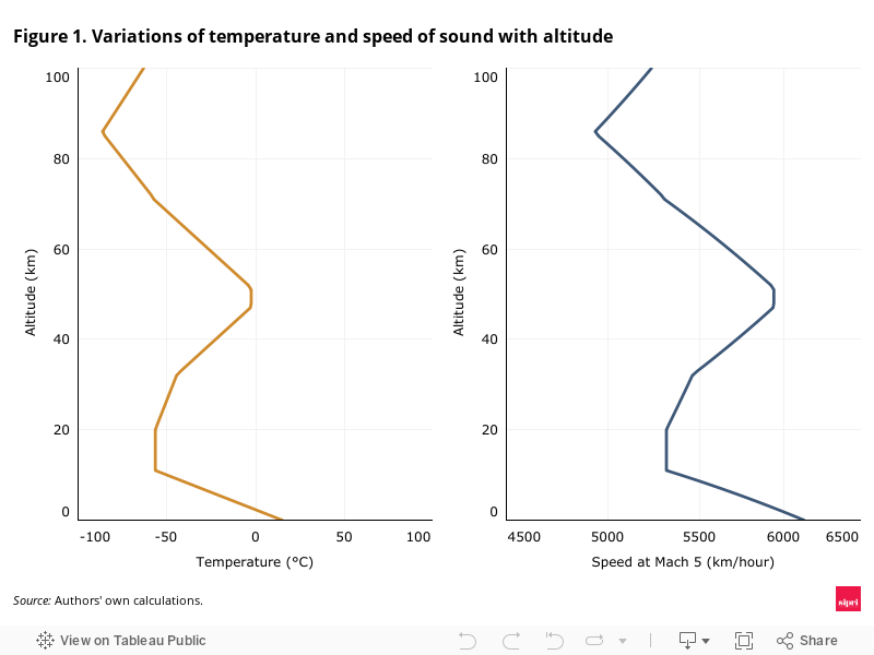
There is also another factor to add to this variation. Since the Mach number strongly depends on the surrounding gas that the object is moving through, using a Mach number for definitions becomes more and more difficult once the surrounding gas gets thinner and thinner—and disappears completely at higher altitudes. While scientists and engineers agree that it still makes sense to talk about Mach numbers at altitudes around 30 km—which weather balloons and special aeroplanes can reach—there certainly is not enough atmosphere at an altitude of 300 km—where satellites are already orbiting the earth. Due to the nature of the earth’s atmosphere, which becomes exponentially thinner with altitude, it is difficult to agree upon a clear altitude limit where Mach numbers should still be used as a measurement of speed, and with that, where hypersonic missiles can sensibly be defined by stating that such missiles travel faster than Mach 5.
Distinguishing hypersonic weapon systems
Hypersonic speed is often pointed to as one of the key factors—if not the key factor—that set ‘hypersonic’ missiles apart from other missiles. However, the speed of ballistic missiles (predating the current hype around hypersonic missiles by almost a century) in many cases far exceeds that of today’s ‘hypersonic missiles’. The ancestor of ballistic missiles, Germany’s A-4 (which later became commonly known as the V-2) was first launched in the 1940s. During ascent, it could reach a speed greater than Mach 5 (although only for a brief period) and could do so again momentarily on its way back down. But, no one would claim that the V-2 was a hypersonic missile. In a similar vein, should one apply this label to modern intercontinental ballistic missiles that reach speeds beyond Mach 20 at ascent and re-entry?
Certainly not, and there are other characteristics commonly cited when defining ‘hypersonic missiles’. However, while a combination of defining characteristics is increasingly adopted among experts, hypersonic missiles are often not well understood within public discussions in politics and the media. Wikipedia, a common starting point for those new to the topic, defines ‘hypersonic flight’ as ‘flight through the atmosphere below about 90 km at speeds ranging between Mach 5–10, a speed where dissociation of air begins to become significant and high heat loads exist.’ However, a V-2 missile would be classified as a hypersonic missile under this definition. The US-based Missile Defense Advocacy Alliance states that ‘hypersonic weapons refer to weapons that travel faster than Mach 5 (~3800mph) and have the capability to maneuver during the entire flight.’ An article published by the Russian International Affairs Council states that ‘there are two major defining characteristics [that] are prerequisite[s] to label a weapon “hypersonic”: Speed exceeding Mach 5 [and the] capability to make maneuvers (both vertical and horizontal) while traveling at this speed inside the atmosphere.’ Many ballistic missiles fall outside of the definition since they do not meet these prerequisites.
Given the speed and manoeuvrability characteristics, hypersonic weapons are further subdivided into two different types of missile systems: hypersonic cruise missiles (HCMs) and hypersonic glide vehicles (HGVs). HCMs keep a constant hypersonic speed (and usually altitude) and are powered over the entire course of their flight. In contrast, HGVs are usually launched on tops of ballistic missiles (often referred to as a boost-glide system) and then glide back through the atmosphere to their target at hypersonic speeds. There are also hybrid cases that do not match either of these categories, but exploring these is beyond the scope of this backgrounder.
It is worth considering the speeds of hypersonic missiles (in this case HCMs) and comparing them with those of ballistic missiles (which may or may not carry an HGV as a re-entry vehicle) to get an idea of how long it takes for both types to reach targets at different distances (see figure 2).
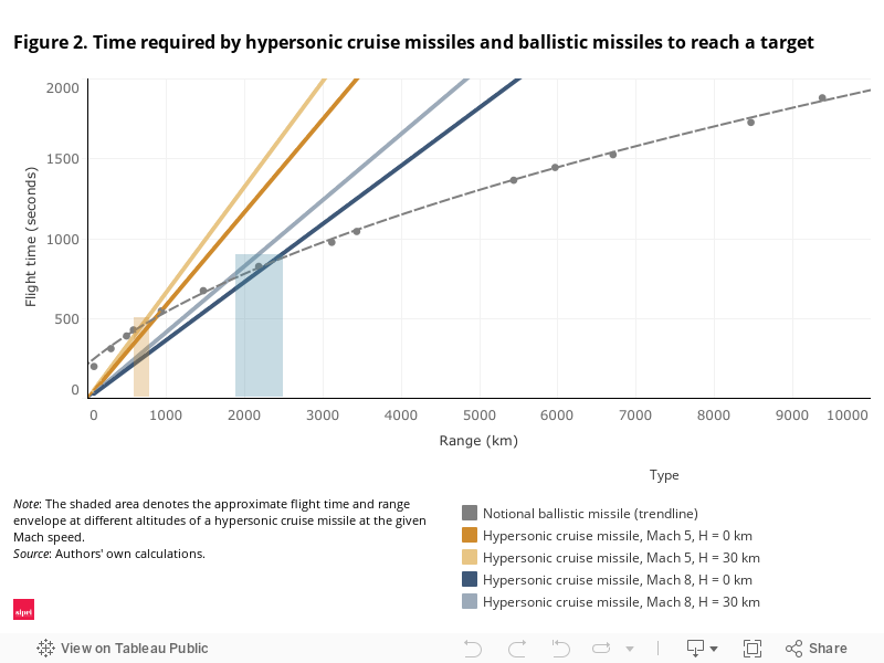
The distance a ballistic missile can fly depends on the speed which it accelerates—the faster it flies, the further it goes, just like throwing a rock. In contrast, HCMs travel at an (almost) constant speed, which is independent of how far away their target is. As illustrated by figure 2, ballistic missiles reach their target quicker than hypersonic missiles at distances beyond roughly 600–800 km for HCMs constantly travelling at Mach 5 (depending on the altitude). Conversely, hypersonic missiles reach their targets faster at ranges of more than roughly 1900–2500 km for HCMs constantly travelling at Mach 8, which is currently seen as the maximum speed they may travel using current technology. This means that HCMs usually take longer than ballistic missiles to reach distant targets. As HGVs are usually carried by ballistic missiles, the time they require to reach a target depends on the trajectory the booster is launched at, the distance covered, and the manoeuvres performed while gliding towards the target.
Speed, manoeuvrability and the characteristics of each of these types of hypersonic missile systems make them more or less suitable for specific military missions and present challenges for missile defence systems. This also influences their possible impact on strategic stability. However, reaching the desired performance characteristics often implied when talking about HGVs and HCMs requires overcoming a range of significant technical challenges.
Subsystems and technology challenges for hypersonic glide vehicles
Any HGV, whether it carries a conventional, nuclear, or no weapon payload, is designed so it can independently perform the necessary manoeuvres to fly precisely into a given target. Sensors and computational capabilities are required to enable the vehicle to maintain a certain degree of autonomy. Consequently, an HGV requires many of the same (or at least similar) basic subsystems a ballistic missile requires, with the exception of the propulsion system. Because an HGV is launched on a rocket booster, it is usually intended to glide towards its target and does not need a main engine.
The main subsystems of an HGV are:
- a guidance and control system;
- a lightweight airframe (with sufficient thermal shielding);
- the payload (for some limited missions, an HGV could potentially rely on the kinetic energy of the impact alone).
As with ballistic missile systems, developing and integrating these subsystems is very difficult. For example, the guidance and control system needs a power source, a computer, sensors, and actuators—such as aerodynamic control surfaces or small cold gas thrusters that enable performing manoeuvres. As one adds the cables, bolts, screws, nuts and elements where these components are affixed, the total weight and the required space increase. There also needs to be enough room to carry the actual payload in most cases. As a result, HGVs are usually neither small nor light, which significantly impacts the capabilities of the overall system and the necessary trade-offs between some of its capabilities.
Any HGV is intended to move through thicker layers of the atmosphere at a very high speed, thus creating a huge heat load and ionizing the air around it. This heat load puts a huge strain on the airframe, which should also be able to withstand any stresses generated by manoeuvres that the HGV is to execute. Also, the plasma cloud generated by the HGV moving at hypersonic speed makes it very hard for any type of sensor to sense anything, let alone to identify and lock onto a target. The HGV, therefore, must know exactly where it is without any help from the outside, thus requiring very precise inertial sensors, among others. The technological challenges of these requirements are comparable to those of a spacecraft designed to re-enter the earth’s atmosphere. But they are even more demanding due to the stricter size and weight limits of HGVs as well as additional requirements derived from their military role.
Designing, building and operating a reliable HGV presents many challenges, including access to technology, high development costs and testing requirements.
Subsystems and technology challenges for hypersonic cruise missiles
The basic requirements for HCMs are similar to those of HGVs, with the exception that the speeds may be lower (even top speeds of Mach 8 have not been convincingly demonstrated yet). In addition, HCMs carry propulsion systems, which have to be highly sophisticated to maintain hypersonic speeds over significant durations. Currently, it seems that only some advanced ramjets and supersonic combustion ramjets (scramjets) are capable of meeting these requirements. Hypersonic propulsion using air-breathing engines over longer distances presents extreme technical challenges. So far, no state has deployed a missile system using a scramjet engine, but research, development and testing continue.
The same basic elements that are required for an HGV (albeit in a very different design) are also relevant for HCMs, with the addition of the propulsion system:
- a guidance and control system;
- a lightweight airframe (with sufficient thermal shielding);
- a highly efficient propulsion system (usually a scramjet);
- the payload.
Adding the propulsion element adds to the problems mentioned for HGVs, as is illustrated by the US X-51A ‘Waverider’ prototype (which would be an HCM). The X-51A was only designed to demonstrate scramjet operations for a few minutes of hypersonic flight without the capacity to carry a weapons payload. At more than 4 metres in length, the X-51A cruiser module was completely packed (see figure 3), with no extra room for a payload. This shows the severe limitations regarding weight and volume for any subsystem elements in HCMs.
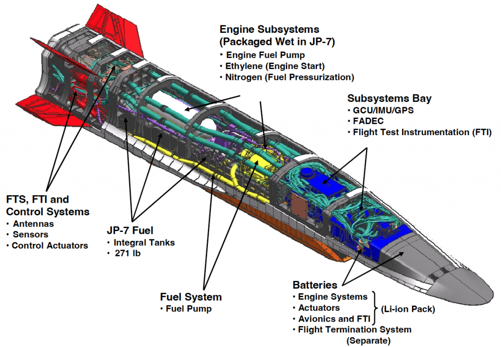
As with HGVs, many of the same technology requirements arise for HCMs. Heat loads may be comparable (depending on the mission), and sensors, as well as the guidance system, have to meet comparable requirements. The sophisticated technology required for a workable scramjet propulsion system is currently a major obstacle for HCM development efforts.
The capabilities of different states’ HGVs and HCMs, respectively, can vary significantly depending on the sophistication of the technology, design and engineering choices. Assessing and comparing the real capabilities of any such systems should thus go deeper than a capability to reach speeds greater than Mach 5 and a certain degree of manoeuvrability.
Conclusions
Returning to the reported hypersonic missile tests by North Korea, in both cases, enabling manoeuvrability appears to be one of the main objectives behind the apparent design choices. Therefore, merely describing these systems as ‘hypersonic missiles’ neither provides the necessary understanding of their actual speed, nor their manoeuvrability or the type of hypersonic weapon system they are. These examples are also a reminder that different degrees of manoeuvrability may be achieved using different types of re-entry or glide vehicles and that speed—and even manoeuvrability—are only two of the key characteristics of a missile system. As North Korea continues its intensive testing cycle, it is important to consider characteristics and types of systems and assess them for their capabilities and possible missions—beyond the ‘hypersonic’ label.
The excessive focus on ‘hypersonic missiles’, particularly in some popular media, paired with a lack of understanding of the limitations of this descriptor, has meant that discussions on the risks created and possible responses have sometimes overly focused on the threat of reduced response times, or impact on missile defences and other countermeasures. Questioning why certain actors—be they states or industry—adopt this terminology can help reveal motivations and vested interests in the hype around hypersonic missiles, i.e. to appear threatening or attract funding. More informed discussions have explored, for example, the potential impact of significant manoeuvring capabilities, including target ambiguity and the evasion of radars and other sensors. In the way that it is currently being used, the term ‘hypersonic’ often has little to no meaning and at the same time fuels competitive dynamics and a fear of missing out on the technology. Overcoming this lack of nuance could help put a brake on some of the competitive dynamics and hype-driven military spending. For example, the capabilities of some existing missiles often already provide the desired capabilities. Conversely, the advantages of future hypersonic missiles over other systems are sometimes exaggerated and come with a large price tag. Considering the technical and economic challenges of developing and deploying viable hypersonic weapon systems can help inform arms control and non-proliferation efforts addressing risks posed by hypersonic missiles.
ABOUT THE AUTHOR(S)

Kolja Brockmann is a Researcher in the SIPRI Dual-Use and Arms Trade Control programme.Dr Markus Schiller
(Germany) is an analyst at Munich-based consulting company ST Analytics.
Researchers make a quantum storage breakthrough by storing a qubit for 20 milliseconds
Researchers from the University of Geneva (UNIGE) broke a new record by storing a qubit in a crystal for 20 milliseconds, a press statement reveals.
The new record in quantum storage could help to develop long-distance ultra-secure quantum telecommunications networks.
Quantum physics has enabled a whole host of innovations, including computers, smartphones, and GPS. The field is also showing great potential by opening new avenues of research for quantum computing and cryptography, with the latter potentially allowing coded messages to be sent over quantum communication networks.
One obstacle stands in the way. After traveling a few hundred kilometers within an optical fiber cable, the photons that carry the qubits (quantum bits) storing the information disappear, ceasing the communication.
The researchers from UNIGE set out to build “repeaters,” a type of “relay” partially based on quantum memory. Their research is published in the journal npj Quantum Information.
Superposition — referred to by Albert Einstein as “spooky action at a distance” — would allow for ultra-secure communication as it would alert a sender as soon as their message has been intercepted, and it could not be copied without breaking the entanglement that allows the message to send in the first place.
In 2015, a team from UNIGE led by Mikael Afzelius, senior lecturer in the Department of Applied Physics, successfully stored a qubit carried by a photon for 0.5 milliseconds in a crystal. The photon transferred its quantum state to the atoms of the crystal before it disappeared. However, the results showed that the phenomenon did not last long enough to build the larger network of crystals required to build a vast communications network.
“A world record for quantum memory”
The new 20-millisecond milestone, however, could be just the breakthrough Afzelius’ team was looking for. “This is a world record for a quantum memory based on a solid-state system, in this case a crystal. We have even managed to reach the 100 millisecond mark with a small loss of fidelity,” Azfelius said.
For their experiments, the researchers kept their crystals at temperatures of -273,15°C so as not to disturb the effect of entanglement.
“We applied a small magnetic field of one thousandth of a Tesla to the crystal and used dynamic decoupling methods, which consist in sending intense radio frequencies to the crystal,” said Antonio Ortu, a post-doctoral fellow in the Department of Applied Physics at UNIGE.
“The effect of these techniques is to decouple the rare-earth ions from perturbations of the environment and increase the storage performance we have known until now by almost a factor of 40,” he added.
The result of this experiment could allow for the development of long-distance quantum telecommunications networks, though the researchers would still have to extend the storage time further. In their paper, the researchers said “the aim is to develop a system that performs well on all these points and that can be marketed within ten years.”
Quantum Memories
Quantum memories are devices that can store the quantum state of a photon, without destroying the volatile quantum information carried by the photon. The quantum memory should be able to release a photon with the same quantum state as the stored photon, after a duration set by the user.
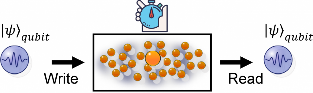
Quantum memories require coherent matter systems, otherwise the quantum information stored inside the medium will be lost due to decoherence. It is also our belief the any practical device should be based on solid-state materials. Rare-earth-ion (RE) doped crystals are highly intersting matter systems for quantum memories, owing to their unique optical and spin coherence properties at low temperaturs (around 4 K).

To cool down the RE crystals we use closed-cycle coolers that do not require any cooling liquids.
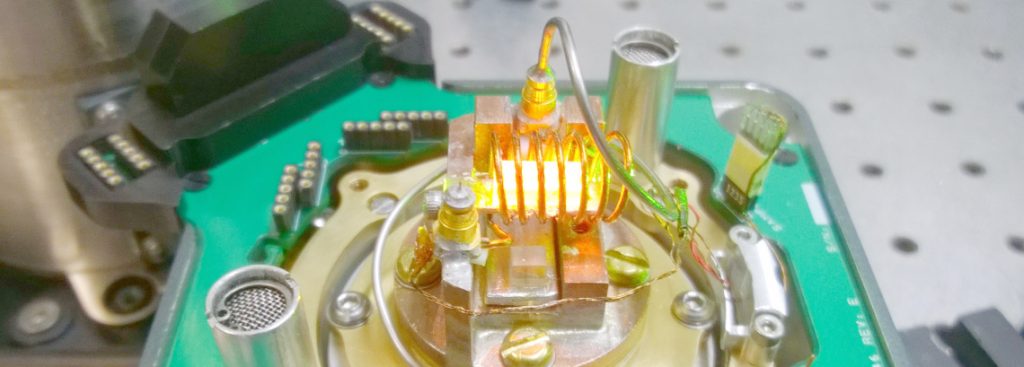
Quantum memories will be key components in future quantum networks, such as quantum repeaters which can provide a solution for long-distance quantum communication beyond the limit of 500 km using today’s technology.
To store photons in RE-doped crystals we use the Atomic Frequency Comb technique, which we first proposed and demonstrated experimentally in our lab in 2008: see PRA article (proposal) and Nature article (experiment).
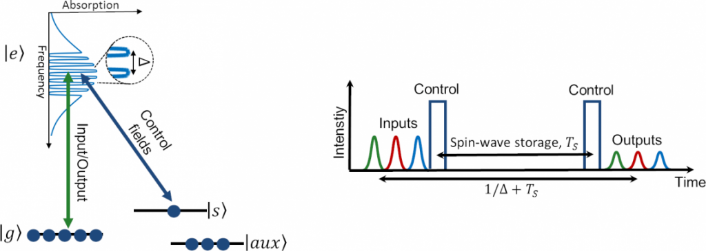
The AFC technique can store quantum information in highly time-multiplexed fashion, which is key to buidling quantum repeaters for future quantum networks.
In addition to future applications, quantum memories are fascinating because they provide a way to study how quantum effects such as entanglement can be transferred between physical systems of widely different nature, eg. between light and matter systems.
Aircraft need to become conscious
Imagine an aircraft with a human-like nervous system, aware of the health of its core organs and covered in a skin which enables it to sense damage and changes in the external environment, such as weather conditions or smoke from an ash cloud, complementing information gathered from existing on-board radar systems.
The aircraft would be able to monitor its own health status and predict maintenance requirements, then plan visits to automated hangars where spare parts are already waiting. A machine that you can have a conversation with, rather like you would have with a human, that can relate to how it is feeling at a high level and suggest what systems may need maintenance, looking after itself through awareness of its own condition.
The cost of aircraft maintenance
Maintenance overall is estimated to make up 10% of airline costs. In 2019, before Covid-19, global MRO spending was US$83 billion, with the projected spend for 2030 anticipated to be US$115 billion (pre-Covid-19 forecast was US$130 billion).
Unscheduled maintenance – where there are surprises, due to such sources as component premature failure – is a major issue with operating cost due to both delays and cancellations. In 2017 alone this amounted to more than US$6.5 billion for wide body jets and almost US$5 billion for small regional jets[1]. Minimizing the time aircraft are on the ground for maintenance also reduces risks from collision damage.
A solution to cut costs
The Conscious Aircraft principle uses sensing, advanced AI algorithms and communication technologies to increase awareness that removes risk and unnecessary costs: avoiding problems caused by component degradation, unforeseen technical failures and human error. With the reduced need for routine, planned maintenance, as well as anticipating the potential for failures, maintenance costs for a Conscious Aircraft would be cut by an estimated 30%[2].
The Integrated Vehicle Health Management (IVHM) Centre is a collaboration between Cranfield University and Boeing, with other core partners including BAE Systems and Thales. Research by the IVHM suggests the Conscious Aircraft is becoming a reality.
The recently opened Digital Aviation Research and Technology Centre (DARTeC) at Cranfield includes a full-scale hangar laboratory housing Cranfield’s 737-400 research aircraft and the provision for aircraft inspection using drones, along with a high-level instrumentation rail to allow camera and other sensors to scan the external surfaces of aircraft for damage.
The hangar lab connects up with DARTeC’s IVHM and digital MRO laboratories, set up to represent an operations control room of an airline or maintenance facility. The digital MRO lab is being used to investigate the use of cameras to inspect aircraft and control robots as they go around an airframe. Rather than relying solely on human experience and judgement, the availability of big data, machine learning and AI will mean more sophisticated and efficient decision-making processes, drawing on a broader range of insights and evidence.
Digital twins
The researchers involved with Conscious Aircraft-related programs of work believe air transport operators could be using such maintenance facilities and conscious platforms within the next twenty years. The research roadmap suggests a working ultra-low maintenance prototype aircraft could be developed by 2035 and a conscious aircraft could enter service by 2040.
Depending on research funding, Cranfield is hoping to have a whole aircraft digital twin available by 2023/4 and a prototype of a digital twin with consciousness – in other words, with reasoning capability – by 2026.
The IVHM Centre is already using digital twins at a sub-system level, for example with environmental control systems to demonstrate more accurate diagnostics and prognostics along with vehicle reasoning.
This includes the capability to monitor the health of passengers and crew as well as the aircraft. The Framework for Aerospace Vehicle Reasoning (FAVER) tool under development at Cranfield is an example of an AI reasoning engine being used to identify how much data is needed to make accurate predictions, and whether information is needed from other systems to find the actual source of a fault, leading to targeted maintenance.
Linking benefits
A key element of making full use of Conscious Aircraft will be advances in the human-machine interface (HMI). It is essential that the interface between the human brain and the conscious aircraft is seamless and facilitates effective and timely decision making – both for pilots and ground-based maintenance engineers.
Another major benefit of self-aware aircraft will be that combined with advanced HMIs – such as brain-computer interfaces, synthetic telepathy, brain enhancement and virtual reality / augmented reality technology – pilots and engineers will be able to communicate intuitively with aircraft. This will enable faster and better decisions when unexpected events occur during flights and reduce the risk of accidents caused by human error.
A longer-term aspiration, arising from a growing understanding of the way the brain works and how it makes decisions, and drawing from developments in cognitive and behavioral science, is to use advanced HMIs to allow pilots and engineers to sense the health of the aircraft as if it was a part of their own body.
Use of data
The Covid-19 pandemic and the associated need for both cost efficiencies and protection for staff, has emphasized the value of autonomous hangar operations. With the conscious aircraft model, data is synchronized with ground-based systems to optimize how the aircraft is managed throughout its lifecycle.
Hangars will become data-driven and based around autonomous technologies, with inspections carried out using a combination of aerial and ground-based robotics. So-called lights out MRO hangars – automated facilities which only switch on when they are needed – will be hubs for remote maintenance engineers to engage with as needed.
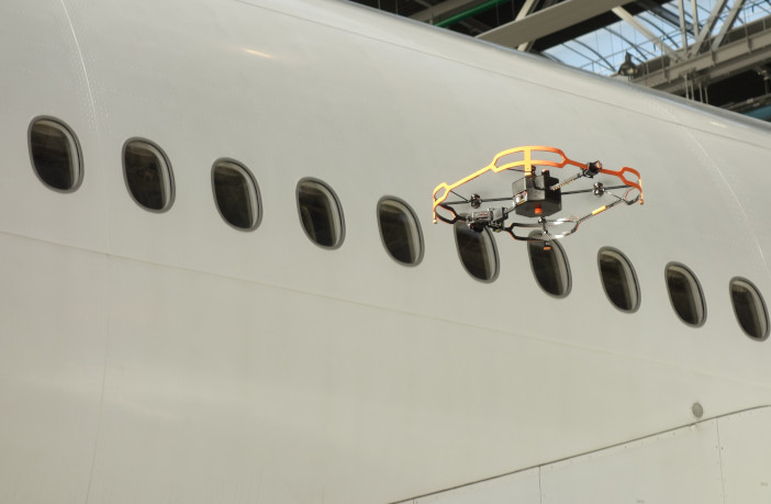
In these hangars, drones equipped with visual and thermal systems that enable non-destructive testing (NDT) will fly around the aircraft structure to locate anomalies and problematic areas both externally and within the structure.
Data from NDT inspections will be analyzed using artificial intelligence (AI) and evidence from digital twins. The simulations will be used to make decisions on airworthiness, assessing whether there is any need for maintenance now and in the future, as well as an immediate fly / no fly decision.
AI safety and security
The use of automation and AI reduces the reliance on human interactions, but AI safety, the verification, validation, security and control of safety decisions made by AI will be critical. Along with facilitating planning for future MRO to minimize operational costs and risks to human engineers, hangars of the future will reduce the risks of aircraft not being available resulting in disruption to services. This will make it more viable for airlines to work with smaller fleets.
The lights out MRO hangar remains a future concept, but research projects are piecing together the necessary elements of technology for integration.
Technical roadblocks at this stage are around ensuring the resilience of the architecture and associated communications, developing the sophistication and safety of applying AI and increasing the autonomy of robotics.
Aside from the technology, there will also be the need for regulatory approval to demonstrate that autonomous systems for maintenance can be as safe as manual, and that won’t be straightforward based on the evidence from the development of autonomous cars. Work will also be needed to create business models that fit the changing industry and market needs.
Another fundamental challenge comes in the form of the digital infrastructure of aviation operations. Data on thousands of health parameters, engine performance, pressure, rotor speeds, temperatures, vibration, can all be communicated to the ground in real-time for health monitoring. The problem is a data bottleneck in aviation: a lack of speed and capacity of data transfer at a cost that makes business sense. Compared with traditional aircraft, the new generation models are expected to produce 30 times more data.
The sector knows its future will be founded on transformational technologies, the third revolution of digital and sustainable tech. But crucially, the success of the third revolution in aviation will also be dependent on the MRO — how those innovations are made part of highly efficient and financially viable operations.
The Conscious Aircraft is going to be a necessary part of any new global system. For this to happen there needs to be a change in mindset, with the long-term potential of the Conscious Aircraft considered at the design stage.
Venus is about to get three major missions in one decade

Venus is about to get three major missions in one decade
Venus has been called “Earth’s evil sister” and many have suggested we terraform the fiery planet into our new home but there is still a lot we do not know about it. This is because only one dedicated spacecraft is currently studying Venus and NASA’s last robotic visitor mission to the planet, called the Magellan mission, ended all the way back in 1994.
This will soon change though as both NASA and the European Space Agency (ESA) have now announced new missions to study the planet, according to Space.com. The announcements were made in June of 2021 but Venus specialists have just started to celebrate them at this year’s Lunar and Planetary Science Conference (LPSC) calling the timeframe of the missions “the decade of Venus.”
Three major missions
“I would like to just take a moment to acknowledge how fantastic it is that we’ve actually moved now from talking about what proposed Venus missions could do to actually talking about what our missions will do at Venus,” Jörn Helbert, a planetary scientist at the German space agency Deutsches Zentrum für Luft- und Raumfahrt, said during an LPSC session this last Tuesday. “This is just an incredible moment.”
The NASA missions will be called VERITAS and DAVINCI, while ESA’s will be called EnVision. VERITAS will hopefully launch in 2027 and will aim to give researchers the first glimpse of Venus’ surface since the end of the Magellan mission. The mission will also seek to collect data about rock composition, geologic activity, and the planet’s core.
VERITAS will also host the Venus Emissivity Mapper which will be complemented by a near-twin fly on EnVision. This mission is targeting launch in the early 2030s. Meanwhile, DAVINCI, which is targeting launch in 2030, will focus on Venus’ atmosphere and is composed of a main spacecraft and an atmospheric probe.
Lateral Instability of Beam – Calculation of critical stress value
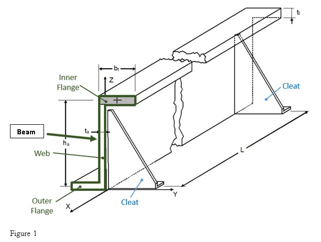
Lateral stability is commonly provided for a beam, a column, or a wall with lateral bracing. Lateral bracing is the structural component that prevents the beam or column from twisting or buckling sideways. Lateral instability is a result of inadequate lateral stability that is the property of an object to develop forces or to have forces imposed upon it that restore it to or maintain its original condition (position). A laterally unstable structure or structural member is able to twist, buckle sideways, or fall over. In the scheme below is shown a typical assembly of a fuselage Frame (that is made up by Inner Flange, Outer flange, Web) of plane, attached to a Panel, between two stabilizers (Cleats). If the Inner Flange of Frame is under the compressive load that it undergoes buckles, it is likely to involve the whole Frame in its deformation. The Cleats are used to minimize the lateral instability and to join the Frame to the panel.
- Equivalent Elasticity
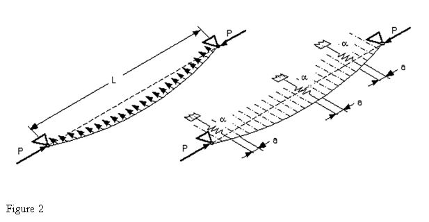
We assume that the Inner Flange of the Frame behaves like a bi-hinged beam at the level of the stabilizers (Cleats). The Cleats are considered as constraints with certain stiffness.
The bending stiffness (around X axis) can be calculated by the following formula:
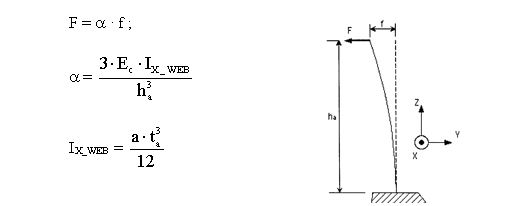
Where:
– α : is the elastic constant of the equivalent discrete supports (see Figure 2)
– IX_WEB : inertia of Web (see Figure 1) around the X axis.
– ta : thickness of web (see Figure 1)
– Ec: Young module in compression
– ha: height of frame’s web
– a: distance separating two equivalent discrete supports (see Figure 2)
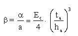
The translational stiffness at the level of the Inner Flange is:
- Instability Stress (Linear Elastic)
The energy method allows us to determine the critical buckling load (see “Theory of elastic stability” by TIMOSHENKO/GERE, paragraph 2.10) by considering the deformation of the elastic line as a sinusoidal series with a wave node at each end of it (the ends are the level of the stabilizers/Cleat).
By minimizing this deformation energy, the lowest critical buckling stress (linear elasticity) is obtained, which is:

with:
• Ec: modulus of elasticity (Compression) of the stiffener
• IZt: minimum inertia of the Inner Flange section
• St: area of the Inner Flange section
• L: distance between Stabilizers/Cleats
• m: number of half-wavelengths
• β: translational stiffness at the level of the Inner Flange
The parameter “m” (number of half-wavelengths) is an integer, greater than or equal to 1, and it depends to the fact that the stabilizers are located at wave nodes by assumption. This number of half-wavelengths “m” into which the bar is subdivided at buckling, can be calculated by imposing condition that the above expression is minimum (making a derivate with respect the parameter “m”). The parameter IZt is the minimum inertia of the Inner Flange with respect to the Z axis passing through the CoG (center of gravity) of the Inner Flange section, and it can be calculated as follows:
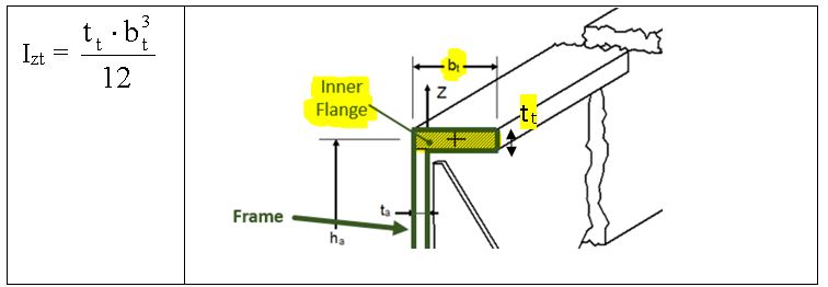
- Determination of m0 by minimizing ”σLateral Instability”
In order to minimize σLateral Instability it is necessary to determine “m” as following:
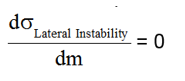
Determination of “m” giving the lowest of the values of σLateral Instability :
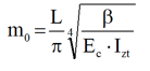
With:
• Ec: modulus of elasticity in compression of the stiffener;
• IZt: Inertia of the Inner Flange with respect to the Z axis;
• L: length of the beam modeling between stabilizers;
• m0: number of half-wavelengths. This number is always greater than 1;
• β : translational stiffness at the level of the Inner Flange
The value of “m0” determined by the equation reported above, could be not be an integer. But it is necessary to have an integer value of “m” to have a wave node at level of the stabilizers. Thus the calculation of σLateral Instability is carried out considering the two closest integer values framing the calculated “m”, and it will be accounted the value of “m” which gives the minimum value of σLateral Instability.
The allowable σLateral Instability calculated with m0≥1 is the buckling stress when the stabilizers are infinitely far each other.
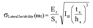
If σLateral Instability (Integer(m0)) > σLateral Instability (Integer (m0 + 1)), then we must take m = Integer (m0 + 1), else m = Integer(m0), with Integer (m0) = integer part of m0. If 1>m0 then we will use the previous equation by taking m=1:

Therefore the final equations to consider for the calculation of σLateral Instability are:
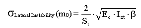
with:
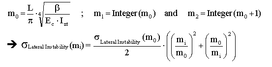
Then we will calculate the critical stress as follows:

- Plasticity Correction
If the value of Afe6eσLateral Instability is higher than 0.5 · Fcy, than it is necessary to consider the effect of plasticity of material by the coefficient η5 :
σ’Lateral Instability = η5 * σLateral Instability
The calculation is iterative because η5 = f (ET,v) = g(σLateral Instability).
The convergence is reached when:
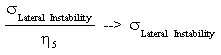
The plasticity coefficient is calculated as the ratio between ET and EC:

With:
- ET is the tangent module, calculated as following:
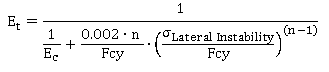
- EC is the Young compression module
In the conception phase, we will make sure to have σLateral Instability ≥ Fcy, in order to use Fcy.
- Numerical Example
Given the following assembly (made up by a Frame and a Panel), calculate the maximum allowable for the lateral Instability.
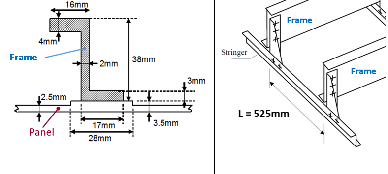
| Material : 7175 T7351 | |
| Tension allowable: | Ftu = 425 MPa |
| Compression allowable: | Fcy = 415 MPa |
| Young module(Compression) | Ec = 72000 MPa |
| Ramberg Osgood coefficient | n = 11 |
Inter-Frame distance is: L=525mm
Step 1: Calculation of St and IZt

Step 2: Calculation of β
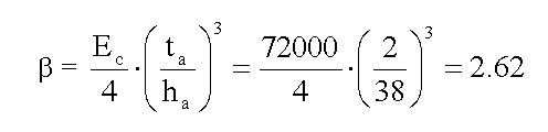
Step 3: Calculation of mo

Step 4: Calculation of Critical Stress
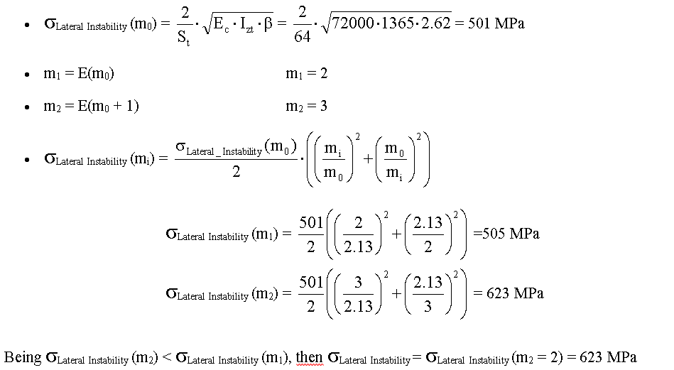
Step 5: Plasticity Correction
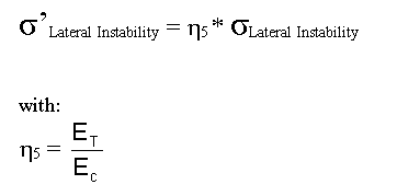
If σLateral Instability≤ Fcy / 2 then ET= EC , otherwise:
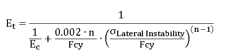
In this case σLateral Instability= 623 MPa > Fcy / 2 = 208 MPa.
To determine the corrected critical stress, the following equation must be solved numerically:
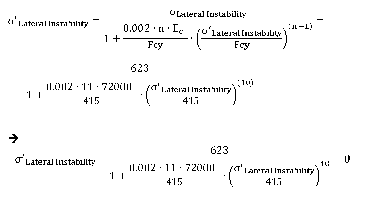
In order to obtain the equivalence reported above, you have to carry out a numerical iteration; it can be done easily by “Goal Seek” function of Microsoft Excel, see below how:

Set the following parameters (see figure below):
“Set cell” = equation reported above
“To value” = 0
“By changing cell” = link to cell to cell where you set an initial value for σ’Lateral Instability (for example to 200 MPa)
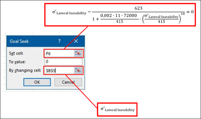
Then click on “OK”, and you will get the final value for the allowable:
σ’Lateral Instability = 353.3 MPa
Amphibious VTOL will reach top speeds of 700 mph
U.S. aviation firm Valkyrie Systems Aerospace received a research grant from the U.S. Air Force to help develop its HoverJet Guardian concept, a hybrid eVTOL, and high-speed jet system, according to NewAtlas.
The USAF is looking to fund concepts for fast-flying VTOL aircraft that could vastly improve its combat and cargo capabilities. The HoverJet Guardian concept is a jet aircraft with an in-built eVTOL system that was designed to provide the high speeds of jet aircraft alongside the added maneuverability of Vertical Take-Off and Landing (VTOL) systems.
Impressively, the machine will be able to run using three different modes, “aircraft, hovercraft, and amphibious.” This means it will be able to land on and traverse over water. Valkyrie also says the aircraft can be flown autonomously or with a pilot. However, the firm has yet to showcase these capabilities to the world and it hasn’t, so far, revealed any prototypes. Still, such flexible usability, alongside the promise of immense speed, is no doubt the reason for strong backing from the USAF.
US Air Force back high-speed VTOL
The HoverJet Guardian concept uses a VTOL system featuring four propellers for take-off and landings. Once in the air, it switches over to a pair of Pratt & Whitney 545c turbofan engines with a combined 8,200 pounds of horizontal thrust. Valkyrie says the configuration allows it to reach a cruise speed of 340 mph (547 km/h) and a transonic top speed of 700 mph (1,127 km/h) when in horizontal flight.
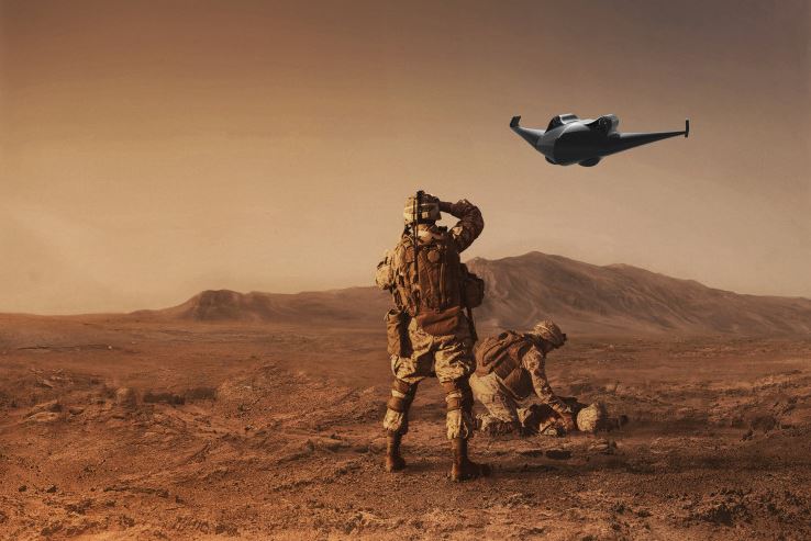
The firm also claims the HoverJet will be capable of 15 hours of endurance at altitudes of up to 40,000 feet (12,192 m). The aircraft will measure 30 feet (9.1 m) long with a wingspan of 24 feet (7.3 m) and it will have a maximum takeoff weight of 12,000 lb (5,443 kg).
The new funding, granted via the USAF’s AFWERX program, will allow Valkyrie to continue the development process for another six months, after which we may finally see a prototype of the impressive-sounding machine. The Air Force has invested in several high-speed VTOL concepts in recent months, including Bell’s high-speed VTOL, or HSVTOL, concept partially inspired by its own V-22 Osprey tiltrotor aircraft.

Researchers develop flying robots with flapping wings
Flapping wing autonomous robots that use a new method of electromechanical zipping that eliminates the need for conventional motors and gears has been developed by researchers in the UK.
The team at the University of Bristol believe that the zipping technology will enable smaller, lighter and more effective micro flying robots to be developed and used in applications such as environmental monitoring, search and rescue, and deployment in hazardous environments.
Existing micro flying robots have used motors, gears and other complex transmission systems to achieve the up-and-down motion of the wings. This has added complexity, weight and undesired dynamic effects.
Taking inspiration from bees and other flying insects, researchers from Bristol’s Faculty of Engineering, led by Professor of Robotics Jonathan Rossiter, successfully demonstrated a direct-drive artificial muscle system, called the Liquid-amplified Zipping Actuator (LAZA), that achieves wing motion using no rotating parts or gears.
The LAZA system simplifies the flapping mechanism, enabling future miniaturization of flapping robots down to the size of insects.
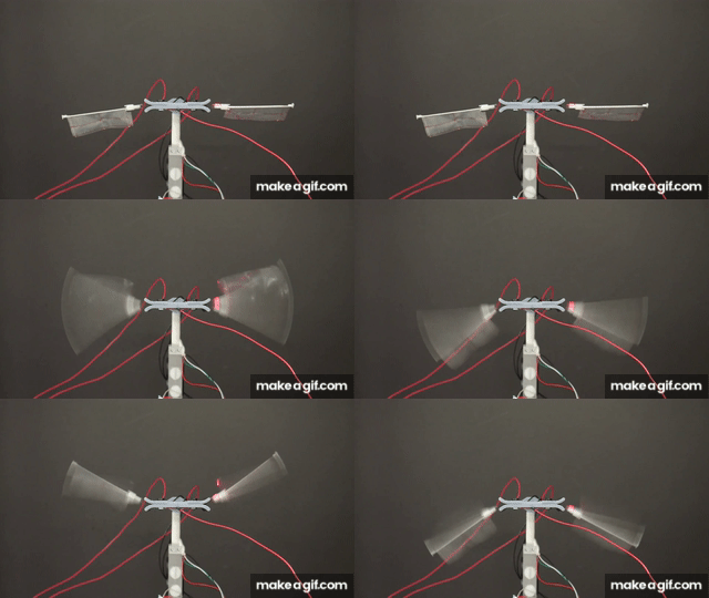
In a research paper published this week the team show how a pair of LAZA-powered flapping wings can provide more power compared with insect muscle of the same weight, enough to fly a robot across a room at 18 body lengths per second.
They also demonstrated how the LAZA can deliver consistent flapping over more than one million cycles, important for making flapping robots that can undertake long-haul flights.
The team believe the LAZA to be adopted as a fundamental building block for a range of autonomous insect-like flying robots.
Dr Tim Helps, lead author and developer of the LAZA system said, “With the LAZA we apply electrostatic forces directly on the wing, rather than through a complex, inefficient transmission system. This leads to better performance, simpler design, and will unlock a new class of low-cost, lightweight flapping micro-air vehicles for future applications, like autonomous inspection of off-shore wind turbines.”
Professor Rossiter added, “Making smaller and better performing flapping wing micro robots is a huge challenge. LAZA is an important step toward autonomous flying robots that could be as small as insects and perform environmentally critical tasks such as plant pollination and exciting emerging roles such as finding people in collapsed buildings.”
New turning point for Lithium-Sulfur batteries, the technology that quintuples the autonomy of electric vehicles
US researchers have developed a particular membrane inspired by biological processes capable of eliminating the main obstacle to the commercialization of lithium-sulfur ion batteries, a technology that has the potential to quintuple the range of electric cars.
In a scientific article published in Nature Communications, researchers from the Michigan Center for Materials Characterization of the University of Michigan have demonstrated a technology that allows to overcome one of the main obstacles to the development of lithium-sulfur ion batteries suitable for use in electric vehicles.
Lithium-Sulfur batteries, as the name suggests, use sulfur as the material for the cathode, one of the most abundant and inexpensive elements on Earth. Not only that: sulfur offers up to 10 times the specific capacity of the normal cathodes used in lithium-ion batteries, with the theoretical possibility of making batteries with an energy density of 2500 Wh / kg, a potential that would allow to reach batteries. much lighter, less expensive and with autonomy up to 5 times higher than the best technology available today. However, there is a big limitation: current Lithium-Sulfur batteries have an extremely limited duration, of the order of about ten charging cycles.
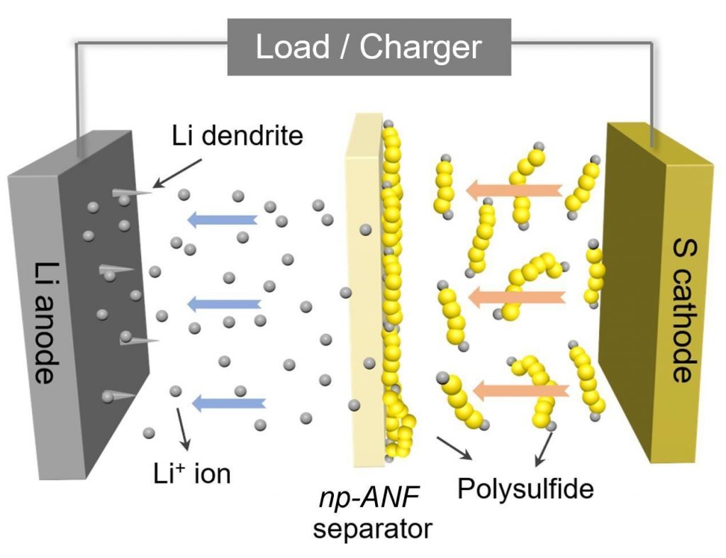
The research conducted by Nicholas A. Kotov’s team has developed a particular porous membrane capable of blocking the main cause behind the reduced longevity of lithium-sulfur batteries, i.e. the formation of lithium polysulphide molecules in the cathode, which migrate towards the anode, covering it, and ending up electrically isolating it, thus blocking the operation of the cell. The researchers drew inspiration from porous cell membranes to create a barrier capable of letting lithium ions pass but blocking polysulfides.
To do this, they developed a membrane made of aramid nanofibers, the same synthetic material used for the production of kevlar. The pores of the membrane capture the negatively charged polysulfides which in turn are able to repel the polysulfides that continue to form on the cathode, letting the positively charged lithium ions pass instead. Furthermore, the stiffness of the nanofibers prevents the formation of dentrites on the anode, another factor that traditionally limits Lithium-Sulfur batteries.
The technology, according to the researchers, solves the main limitations of lithium-sulfur batteries without compromising other parameters, such as charge density. The material developed is suitable for the temperatures reached by the cells for the automotive sector and would be able to offer up to 1000 charging cycles even with fast charging, sufficient to guarantee a battery longevity of the order of 10 years. The innovation featured in the study was patented by the University of Michigan, and Kotov is founding a start-up to bring the technology to the battery market.
Why planes have no parachutes for every passenger?
If there is a lifesaver for every seat like a parachute, why do not use it? The most anxious people about flights may have thought about it: wouldn’t it be reassuring to have an emergency parachute in the safety equipment of each passenger?
Perhaps, if we knew how to use them and if the hundreds of people on board had any chance to deploy them neatly as they exit the aircraft. The reality is that the passenger on a commercial flight has a much better chance of surviving by remaining seated and adopting the safety arrangements already in use.
UNPREPARED. Jumping with a parachute requires coldness, the preparation necessary to maintain the right position during jumping and flying, as well as several minutes of preparation to put on the device correctly. They are all impractical conditions, due to accelerations, jolts and speed of a jet in danger.
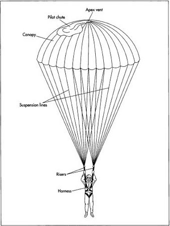
FROM THE FRYING PAN TO THE FIRE. The risk of opening it in the cockpit, with serious consequences on the stability of the aircraft and on the safety of passengers, would be very high, not to mention that the normal emergency exits of airliners are not suitable for this type of launch: it would easily end against a wing, or against the tail (a special ramp at the rear of the cabin would be needed).
WEIGHT FACTOR. Parachutes are also heavy and expensive, would require constant maintenance and would add ballast to flights, which would become even more expensive.
IMPOSSIBLE OR ALMOST. In short, in order for a personal parachute to be of any use, it would be necessary to be in a condition of slow failure, in broad daylight and above the ground, with all the time necessary to prepare and moreover with an aircraft equipped with special exits for launches: a situation that could hardly occur.
Inter-Rivet Buckling
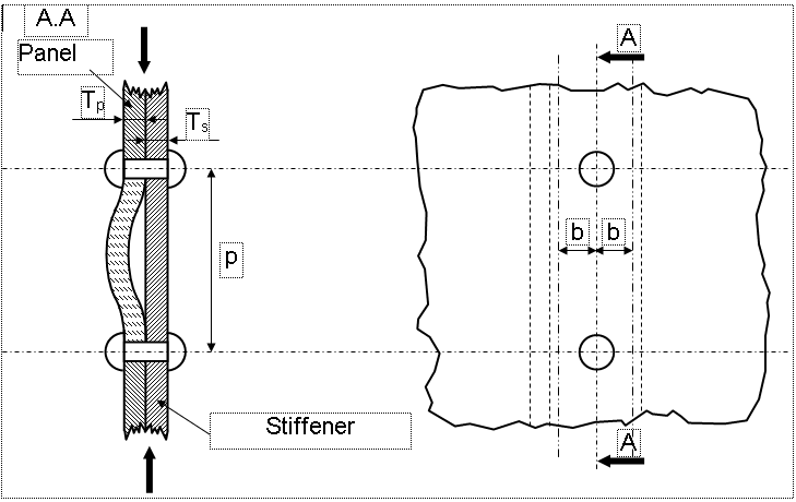
The phenomenon of inter-rivet buckling occurs when there is a localized buckling or instability of the panel (or of the flange of the stiffener) between two consecutive rivets, it can occurs if the panel is stressed in compression.
In order to prevent this phenomenon, the compressive stress in the panel (or in the flange of the stiffener) will be limited to a value that will be defined as allowable stress.
- Assumptions
We consider a sheet metal strip (Stiffener) with width 2b is jointed to a panel.
- Critical Stress
The allowable stress for Inter-rivet buckling can be calculated by the following formula:
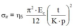
With:
• Ec: compression modulus of the material (normally the minimum one is used between the parts attached).
• ƞ5: plasticity correction coefficient, it is equal to: ƞ5 = Et / Ec
• K: coefficient that depending on the type of fasteners used
• p: pitch that is axial distance between rivets
• t: thickness of the attached elements considered (Panel, Stiffener, etc.)
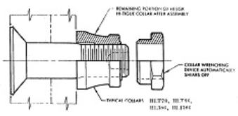
Tests have shown that depending on the type of fasteners, the binding conditions at the ends of our column change. The boundary conditions are between the hinged (K = 1) and constrained condition (K = 0.5).
For example for bolts, the usual value is K=0.50.
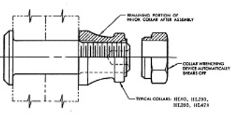
Instead for bolts or rivets instead the value is K=0.65.
- Numerical Example
The junction between stiffener’s flange and a panel is ensured by countersunk screws with a pitch=22mm; below are reported the data for the calculation:
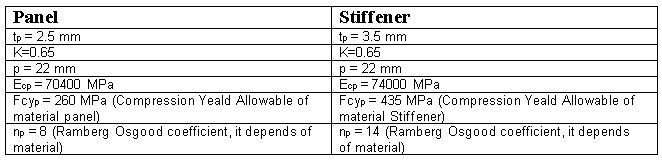
By considering the formula explained above, the Inter-rivet buckling allowables for each part are:

For the panel, the plasticity correction coefficient is calculated as follows:

With:

Therefore:
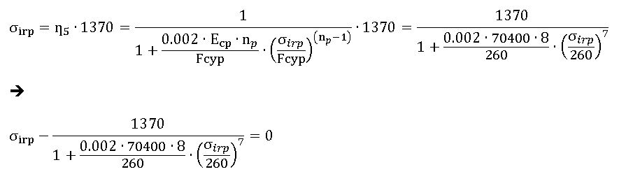
In order to obtain the equivalence reported above, you have to carry out a numerical iteration; it can be done easily by “Goal Seek” function of Microsoft Excel, see below how:

Set the following parameters (see figure below):
- “Set cell” = equation reported above
- “To value” = 0
- “By changing cell” = link to cell to cell where you set an initial value for σirp (for example to 200 MPa)
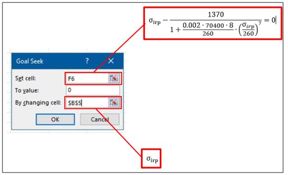
Then click on “OK”, and you will get the final value for the allowables.
So final values for inter-rivet buckling allowables for panel and stiffener are:
σirp =259.55 MPa
σirs =439.38 MPa
Usually is taken the minimum between the σirp /σirs and Fcy as allowable. This allowable is compared with the maximum compression stress of attached parts.