The Different sources of Residual Stresses
The significance of residual stresses for fatigue is important in various practical problems. Unintentional tensile residual stress can have an adverse effect on the fatigue resistance, while compressive residual stress can significantly improve the fatigue behavior. Residual stresses can be present in a material as a result of different processes. The main ones are listed below:
(1) Inhomogeneous plastic deformation, in many cases at notches
(2) Production processes
(3) Shot peening
(4) Plastic hole expansion
(5) Heat treatment
(6) Assembling components
- Inhomogeneous plastic deformation
A simple theoretical model will be discussed first. In figure below two tension bars of different lengths are connected to the same infinitely stiff clampings at the ends. If a load is applied to this 2-bar system, the elongation Δl is the same for the two bars. As a consequence, the strain ε in the shorter bar will be larger because its length is shorter. In view of the larger ε, the stress will be higher and the bar thus will carry more load than the other bar. This is shown in the load-displacement diagram in figure below. There is a
load concentration in bar 1. Assuming that both bars are similar, it implies that permanent plastic deformation can occur in bar 1, while bar 2 is still fully elastic.
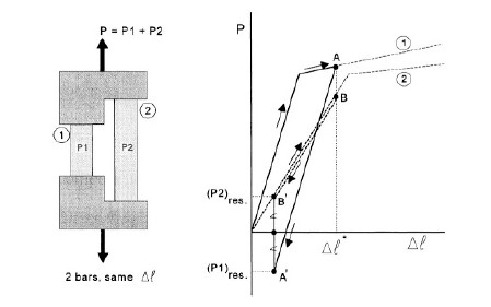
This occurs at points A and B where Δl = Δl*. During reversion of the loading direction elastic unloading occurs in both bars, from A to A’ in bar 1 and from B to B’ in bar 2. After full unloading P = 0, which means that the sum of the residual loads in the two bars is zero; and thus (P1)res = (P2)res, see figure above. Because of the plastic elongation of bar 1, this bar is longer than it was before. As a result, it will be in compression at P = 0 while bar 2 will be in tension.
Residual stresses have been introduced as a result of plastic deformation in one part of the 2-bar system.
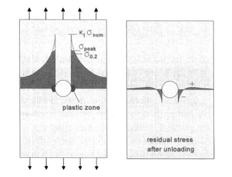
A similarly inhomogeneous plastic deformation occurs in a strip with a hole loaded in tension, see figure below. If a high load is applied to the specimen, σpeak at the edge of the hole exceeds the yield limit, and a small plastic zone is created at the root of the notch. As a consequence of the plastic deformation, σpeak is smaller than Ktσnom. The peak of the stress distribution is flattened by local plastic yielding. In the plastic zone permanent plastic deformation has occurred. The plastic zone is elongated; it is larger than it was before. After removing the tensile load on the strip, i.e. in the unloaded condition, the elongated plastic
zone will be under compression. It does no longer fit stress-free in the elastic surrounding which tries to constrain the permanent plastic deformation. A residual stress distribution is introduced with a residual compressive stress at the root of the notch, which is the fatigue critical location under cyclic loading. The residual compressive stress is balanced by residual tensile stresses away from the notch. The residual compressive stress at the root of the notch can be very favourable for fatigue. In general, local plastic deformation causes an inhomogeneous residual stress distribution as illustrated by the right hand picture in figure below.
- Production processes
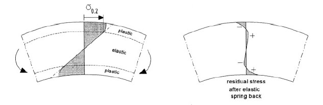
Two common production processes are cold working and machining. Cold working implies that the material is plastically deformed, which should leave a residual stress distribution in the product. An elementary example is plastic bending. As illustrated by figure below, a bending moment will induce plastic deformation in the outer fibers of the material. After unloading, elastic spring back occurs, and a residual stress distribution as schematically presented in figure below will remain in the material.
In a similar way, residual stresses can exist after a variety of cold working processes. Forging in many cases is a hot-working process, which still can leave residual stresses. The same is true for rolling of some product forms starting at an elevated temperature. Rolling for sheet straightening is done at room temperature. Rolled sheets and plates may carry a residual stress system.
It is not always realized that machining operations can also introduce residual stresses. Metal cutting implies removal of a layer of material, which includes a failure process near the tip of the cutting tool. But the failure process is preceded by plastic deformation. Depending on machining conditions (sharpness of the cutter, feed rate, depth of cut, etc.) and the material, residual stresses can be significant, although they only occur in a thin surface layer.
- Shot peening
Shot peening is a well-known process to introduce favourable residual stresses in the material surface of a component. In various practical cases it is applied to prevent fatigue or stress corrosion problems. The peening operation implies that the surface layer of a material is plastically stretched by blasting hard particles (shot) onto the surface of a component. Because this layer must remain coherent with the elastic substrate material, residual compressive stresses are introduced at the surface. It can lead to warpage of the component, although dimensional distortions can sometimes be prevented by a symmetric peening operation.
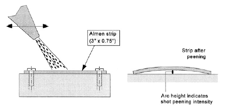
The intensity of the peening operation can be checked by peening a so-called Almen strip, which is a steel strip (3″×0.75″, 76mm x 19mm). The strip is fixed by bolts to a stiff foundation, and peened under well defined conditions from one side only, see figure below.
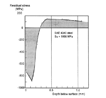
After removing the bolts, the strip is curved. The arc height is measured, which gives a direct indication of the shot peening intensity. An example of a residual stress distribution obtained by shot peening is shown in figure below for a high strength steel, which is fatigue sensitive. Surface rolling is another process to plastically deform the material surface. It can be applied locally to the notch root area, e.g. to the root of a fillet radius.
- Plastic hole expansion
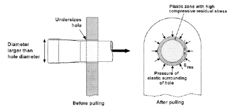
Plastic hole expansion has been developed to improve the fatigue resistance of holes, also for bolted and riveted joints. The hole is drilled with a slightly undersized hole (a few % too small). A tapered pin is then pulled through the hole to expand the hole, see figure below. As a result, plastic deformation does occur around the hole. The plastic zone has been stretched tangentially and pushed outwards in the radial direction. The plastic zone has a larger diameter than before. It implies that the elastically strained material around this plastic zone will exert a pressure on the zone, see figure below, which causes tangential residual
compressive stresses around the hole. The method is very effective for improving the fatigue resistance because the residual stresses can be high, i.e. almost in the order of the compressive yield stress. Moreover, the depth of the plastic zone can be a few millimeters (compare to the small depth in figure above). Small distortions of the cylindrical shape of the hole can be corrected afterwards by reaming, which hardly reduces the residual stress.
Commercial apparatus has been developed for hole expansion, and a large favourable effect on fatigue can be obtained.
- Heat treatment
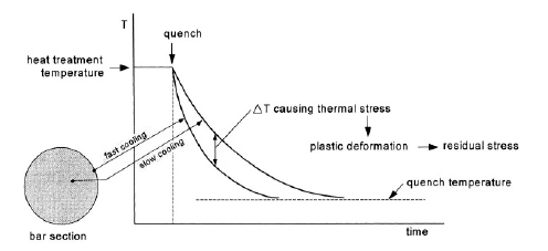
Quenching is an abrupt step of many heat treatments applied to alloys of various materials. Cooling usually occurs very fast at the outside of a component, see Figure 4.8, and significantly slower inside the material. The inhomogeneous cooling introduces thermal stresses. The faster thermal contraction at the outside causes local tensile stresses balanced by compressive stresses inside. At the still elevated temperature, the yield stress is low and plastic deformation can easily occur. Residual stresses are then introduced.
In the rotational symmetric case of Figure 4.8 it should lead to the favourable situation of compressive residual stress at the outside balanced by tensile residual stress inside the material. Unfortunately, many components have complex shapes which makes it difficult to know the residual stress distribution obtained after quenching. Tensile residual stresses, also at the outside, are possible. They can be reduced, or even reversed, by shot peening.
- Assembling stresses
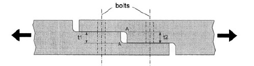
The previous examples of sources of residual stresses were associated with inhomogeneous plastic deformation. A completely different category of residual stresses in a structure is due to assembling of components to form a single structure. In many cases, bolted connections are involved (also welding). The residual stresses in the structure depend on the dimensional tolerances of the components. A simple example is shown in figure below. If t1 and t2 of this joint are not exactly equal, and the bolts are fastened, the misfit will introduce bending. Maximum internal stresses occur at the root of the fillet notches A in figure below in the still unloaded joint. In this case the term “internal stresses” appears to be more correct. These stresses due to assembling a structure are also referred to as built-in stresses. The occurrence of the stresses can be avoided by a strict tolerance system.
In special cases, built-in stresses are desirable. This applies to bushes pushed with an interference fit into a hole, and to prestressed bolts.
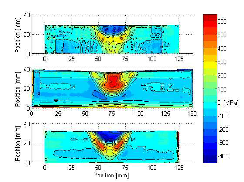
Below instead is shown welded residual stress distributions measured by the contour method.

Hibernation experiments for space travel
Two Russian companies want to launch hibernating organic material into orbit in order to study its behavior
The United States and Russia recently signed a collaboration agreement to build the space station in lunar orbit: it will be the first step in the exploration of the Solar System, in particular Mars and other long-term journeys.
Getting to and from the Red Planet, staying there (in orbit or on the surface) for six months, would take the crew for a couple of years. Towards Jupiter and Saturn, or even beyond, we will have to consider much, much longer times: tens of years, tens and hundreds of centuries. Assuming such voyages are feasible, how can the crew survive for so long?
A path that science fiction has always traveled through is hibernation, now also reconsidered by science, after the experiences of cryopreservation.
Two Russian companies, KosmoTech and KrioRus (which has been offering post-mortem cryopreservation services for years), deal with hibernation with investments and experience, which a few weeks ago created the Consortium Space technologies with the aim of “investing in the development and implementation of advanced space technologies “, including hibernation.
The first step of this project will consist in sending into space containers with biological material, human and animal, and samples of single organs and DNA, in order to verify the effects of microgravity conditions on organic parts subjected to hibernation.
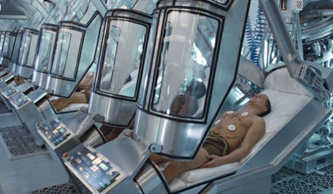
In this experimental phase, the consortium also aims to develop the technologies necessary for the “repair” of any damage to living organisms that may occur in space. The project does not precisely define who will be in charge of launching the material, but they should be very important companies in the Russian aerospace sector.
KrioRus seems to have considerable commercial experience in cryonics: from the documents available on the site it can be deduced that from 2003-2005 to date it has conducted the cryopreservation of 54 whole bodies and (human) brains, as well as an uncertain number of dogs, birds and cats. Recently among its services was added that of the perennial cryopreservation of the brain in Earth orbit, at a price of 250,000 dollars (it is not clear whether including the launch price).
Of course, cryopreservation and hibernation are very different things: the first applies to the deceased, the second would apply to the living with the certainty of being able to wake them up healthy and functioning … Unfortunately human hibernation and relative awakening at the moment , we know little or nothing: if you cannot calmly wait for the progress of science to find out more, you can always resort to the services of KrioRus.
The Mysterious Object Orbiting TIC 400799224 that baffles astronomers
The anomalous behavior of two bodies belonging to the binary system TIC 400799224, rotating around each other, is perplexing astronomers. For now they are only hypotesis.
About 2,300 light years away from us there is a “mysterious object” (called TIC 400799224) which periodically shows a decline in brightness that lasts about 4 hours, after which it returns to normal conditions.
The first explanation sketched by astronomers hypothesized that it was an eclipse linked to transits of planets or asteroids, but more in-depth analyzes have ruled out this: there is something that is not easy to explain.
THE CATALOG. This “variable” object was discovered thanks to the Transiting Exoplanet Survey Satellite (TESS), launched in 2018 with the aim of discovering small planets around the stars closest to the Sun. It has so far discovered 172 confirmed exoplanets and compiled a list of 4,703 exoplanets. “candidates”, which have yet to be studied to confirm whether or not they are planets from other stars. Its extremely sensitive camera takes images that cover a huge field of view, so much so that it creates a catalog with over 1 billion objects, from pulsating stars to supernovae, from disintegrating planets to binary stars to triple and triple star systems. even more.
What attracted the attention of Karen Collins, an astronomer at the Harvard-Smithsonian Center for Astrophysics, and of the team that would have discovered TIC 400799224, was its behavior, completely anomalous compared to other star systems. This unusual source, in fact, showed a rapid and noticeable decline in brightness – almost 25 percent in just four hours – followed by multiple variations in brightness in the following hours, and then resumed normal lighting conditions.

THE TEST. Collins then decided to do a research to see if other telescopes had already observed it without further studying it. Thus, by crossing the available data, she was able to understand that the object is probably a binary system (ie formed by two objects in reciprocal rotation) and that one of the objects pulses with a period of 19.77 days.
In her work, he therefore hypothesized that it is probably an orbiting body that periodically emits clouds of dust that obscure the other star. But while the periodicity is strict, the star’s dust occultations are irregular in shape, depth and duration.
DISCONCERTING! The nature of the orbiting body is disconcerting because the amount of dust emitted is enormous and if it were the product of the disintegration of an object, such as the asteroid Ceres in our solar system, it would have survived only eight thousand years before disappearing completely.
But that doesn’t apply to that object (unless it has only recently begun to emit dust, in astronomical terms).
So what? The researchers now plan to continue to monitor this object and to cross-reference the data with historical observations of the sky, to try to better determine the variations that have occurred over the last few decades.
The lunar caves could house human colonies
Numerous lunar caves discovered thanks to the images of the probes present stable conditions: they could host future colonies of explorers
When, in the Sixties, the first images taken by the probes that had approached the Moon arrived, some caves were identified that from the surface penetrated into the lunar crust. It was understood almost immediately that those lunar caves were the result of the collapse of the roof of “lava tubes”, structures that had formed when the lava flowed there.
DOWN THE ROOF. On its way, the upper part cooled quickly forming a tunnel inside which the lava continues to flow until the end of the eruption. In many cases the end result was a real tunnel that ran for hundreds of meters or kilometers. Somewhere the roof collapsed in some places, giving rise to openings that allow you to enter these caves.
Now the CU Boulder researchers have decided to test what the environment inside some of those caves might be like. The preliminary results of the working group suggest that the environmental conditions within those structures are remarkably stable. “They don’t seem to be experiencing the large temperature changes that the satellite’s surface is normally subjected to,” said Andrew Wilcoski, of CU Boulder’s Department of Astrophysical and Planetary Sciences.
Yes, because “as you approach the equator, surface temperatures can reach and exceed 100 degrees Celsius during the day and drop as low as 170 degrees Celsius below zero at night,” Wilcoski said. The temperature in the caves, on the other hand, seems to support relatively stable environments.
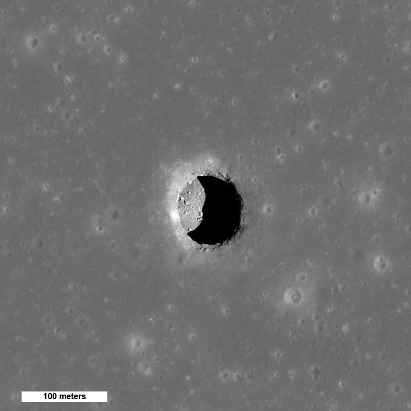
THE ENTRANCE. A simulation showed that most caves could have temperatures between –120 ° C and –70 ° C during the entire lunar day (which lasts approximately 28 days). It is worth bearing in mind, however, that near the entrance to these caves the conditions are greatly influenced by the way in which the sun’s rays arrive.
Wells and caves are potentially ideal locations for the space colonies of the future. They are naturally welcoming places where men could be protected from the dangerous radiation of the Sun and space in general, as well as from meteorites, even small ones, which reach the surface intact on the Moon since, unlike the Earth, there is no atmosphere capable of burning them.
The question is whether in these caves there may also be resources useful to astronauts during their stay, such as ice from which water could be obtained to drink, to use for personal hygiene or to produce rocket fuel.
NO WATER, BUT … The computer simulations, however, say that these are not the places to look directly for water. An interesting possibility, would be to establish a protected base inside a lunar shaft or cave that is near one of the polar craters containing water ice and use it to store the ice collected outside.
At the moment, no one knows how many wells and caves might be hiding on the moon. A survey carried out a few years ago, analyzing with great attention the lunar photos available, found more than 200. Most of them were between 400 meters and a few meters wide. All in all suitable, therefore, to be able to host an entire human base within them.
Wind hydrogen, Siemens Gamesa and Strohm collaborate to create a hydrogen transport system produced directly by marine wind turbines
Work has begun to develop the pipelines for a new generation of offshore turbines capable of supplying wind hydrogen. The initiative is the result of the agreement signed at the beginning of December between the Spanish multinational Siemens Gamesa and the Dutch manufacturer of composite pipes Strohm. An agreement that could take a step forward in the project launched by Siemens Gamesa.
The company has in fact joined forces with Siemens Energy to build new marine wind turbines equipped with electrolysis systems; highly integrated systems that store the electricity produced by the blades directly in the H2 vector. And in time of need they send it ashore via submarine conduits.
is it feasible? For now, the project is still in the early stages. The multinational’s engineers are adapting the SG14-222 DD, currently one of the most powerful turbines in the world, to generate wind hydrogen. A job that will also require the development of a system for the desalination of sea water.
“Siemens Energy is developing a new electrolysis product that meets the needs of the harsh offshore marine environment and is perfectly synchronized with the wind turbine,” the company website reads. “The developments will serve as a test bed for large-scale and cost-effective hydrogen production. And they will demonstrate the feasibility of a reliable and effective implementation of modular systems from wind to hydrogen “.
Pipes instead of power lines
In this context, the agreement with Strohm will make it possible to complete the technological framework. How? Developing ad hoc solutions for the transfer of the carrier to the ground. The Dutch company is now the world’s first and largest producer of fully bonded thermoplastic composite pipes, elements that could prove particularly suitable for the submarine transport of this gas. The technology, in fact, resists corrosion and stress, offers innate flexibility and can be easily connected to the system. Guaranteeing over 30 years of maintenance free operation.
Explains Finn Daugaard Madsen, head of innovation – Power to X at Siemens Gamesa. “We believe in the potential of green hydrogen and have been working on the concept of decentralization for some years. Strohm has supported us through several case studies, identifying solutions that can be readily used by completing our systems. This partnership will help us innovate together in an open format, accelerating the availability of green H2 ”.

Angara-A5 is the Russian rocket which, after the engine failure, risks crashing to Earth: alarm from space agencies
There is a new threat to the Earth directly from space. No, we are not talking about an alien invasion or spaceships, but a Russian rocket in free fall towards our planet.
This is precisely the Angara-A5, a russian rocket produced in Moscow, and which was launched into space last December 27 from the Plesetsk base, in the northwestern region of Arkhangelsk. According to reports from the experts, the same should fall back on the earth, in a totally uncontrolled way, in the next 24 hours, consequently it is not clear where it can land, and what damage it could do. The rocket was launched into orbit to test a higher stage of the rocket, but the experiment evidently did not work, and everything did not go as the engineers had predicted on the ground. According to what has been specified by TAS, the Russian state news agency, “within 24 hours the rocket will be in free fall, but no one can predict where it will fall”.
It must be said, as often and willingly happens in the case of space debris, that most of the debris burns in contact with the earth’s atmosphere, disintegrating due to high temperatures, but it cannot be ruled out that some part larger than the Angara-A5 itself, can cause damage if it manages to overcome the “space barrier”, then coming into contact with our planet. The rocket was launched on December 27, 2021, and after a few hours of launch, two mandatory maneuvers had been performed which caused an engine failure. According to Holger Krag, head of the Debris Office of the European Space Agency (ESA), some damage cannot be ruled out at all: “It will certainly arrive here within the next 24 hours, but where no one can say, because in the next few hours it will carry out several revolutions around the globe “.

Krag himself, quoted by the American broadcaster CNN, continued: “The part of the Russian rocket was traveling at 7.5 kilometers per second and its re-entry latitude was probably between 63 degrees north and south of the equator.” The US Space Command also expressed itself on the matter, which through a statement confirmed that “it is monitoring the position of the body of the Angara A5 / PERSEY rocket in space”, and assesses at this moment that “the point of entry into the atmosphere terrestrial is over the South Pacific Ocean ”. Something similar happened in May 2021 when NASA publicly criticized China for failing to take care of rocket safety standards: in which case some debris fell into the Indian Ocean without causing damage.

How engineers test hypersonic weapons and vehicles
Flying faster than Mach 5 is an old idea. During the 1950s and 1960s US hypersonic flight research programs such as the X-15 rocket plane were the first to test the concept. Intercontinental Ballistic Missiles, which re-enter the atmosphere at hypersonic speeds were also developed around the same time.
During the decades since then several hypersonic vehicles have been developed for research, then shelved by engineers. But in the last five years there has been a resurgence in interest in flying faster than 3,000mph (4,800km/h) primarily in the USA, Russia and China.
For the first time commercial companies, such as UK-based Reaction Engines have made solid progress developing air-breathing engines. The hope is that in the future these engines will enable “spaceplanes” to fly through the stratosphere and above at hypersonic speeds. However, most actual testing activity for hypersonic flight remains focused on single-use weapons systems.
There are at least 18 military hypersonic projects around the world. It is estimated by market analysts that between 2015 and 2024, the US Government will spend almost US$15 billion developing hypersonic technologies and weapons systems.
Ground testing
There are two main types of hypersonic weapon systems currently. Hypersonic glide vehicles (HGV) are launched from a rocket, probably an existing ICBM, before gliding down to a target. Hypersonic cruise missiles are powered by high-speed, air-breathing engines, also known as scramjets, after they acquire a target.
The first testing phase for both types of system is extensive ground testing. There are very few facilities capable of testing hypersonic concepts and technologies. Northrup Grumman’s Aerothermal Research and Testing facility in Ronkonkoma, New York, is one of them.
Dan Cresci is chief engineer in charge of test services at that facility and has worked for Northrup Grumman in the area of supersonics and hypersonics for 35 years.
Engineers like Cresci have been dealing with hypersonic testing for decades in the form of rocket and rocket assist-powered propulsion experiments. According to Cresci, interest and research into hypersonics and airbreathing propulsion has “ebbed and flowed” in the years since then. But, the many programs have all had one thing in common – they have been firmly in the R&D phase and focused on propulsion.
Hermeus is working with NASA on an air-breathing hypersonic engine, the core of which is a GE J85 engine
“The difference is now we’re closer to actually developing these technologies into operational systems – weapons, space vehicles and manned aircraft,” Cresci says. “In the testing world that means we are doing longer duration tests, at higher speeds and testing a variety of technologies together in a single test.
“We’ve solved many of the technical challenges around propulsion and we’re moving on to test materials, controls and guidance systems. We have six different cells, each with capabilities for focusing on a different aspect of hypersonic flight ground testing.”
Tests recreate as closely as possible the conditions that will be experienced during flight. The data from the testing is used to refine models that predict hypersonic flight performance. Tests differ in size, from running entire engines in cells to subjecting coupons of materials to extremely high temperatures and pressure gas flows from a nozzle. Tests generally run for between 30 and 120 seconds.
“Our objectives – one of everyone’s objectives – is to run tests for as long as possible, because the operational systems will have flight times of many minutes and more,” says Cresci.
For propulsion testing, engineers are measuring the same key parameters they were 20, 30 years ago: pressure, temperature, airflow, fuel flow and thrust. Materials testing usually focuses on thermal structural interactions, with engineers looking for and measuring deformation patterns if the materials are ablative.
Simulating these hypersonic test environments requires high-temperature combustion of hydrogen, oxygen and air from a complex system of plant controls and massive sets of storage tanks. To simulate high altitude flight, the Ronkonkoma site also has a large vacuum sphere, similar to the chambers used to test space vehicles. A recently added ejector system has increased the vacuum sphere’s run time.
One of the fundamental changes to testing to happen during Cresci’s career is that the amount of data generated has increased substantially. “Over the years the density of measurements has increased probably ten times,” says Cresci. “Accuracy has increased significantly and we can compare pre-test CFD [Computational Fluid Dynamics] predictions much quicker.
“It means the iterative process of development can move a lot faster – we understand things like flow fields and engine response in the hypersonic domain much better.
“We always want to have a higher fidelity test, so investment focuses on upgrading instrumentation and data acquisition networks to obtain higher rates of data. It’s all about getting to flight. Ground testing always generates more data than flight testing, where costs and planning increase a lot.”
Flight time
Paul Cook is director of missile systems at Curtiss-Wright Defense Solutions (CWDS), a major supplier of instrumentation and data acquisition solutions to hypersonic projects.
Flight testing for weapons systems, including hypersonic ones, is done in phases – an early short-range flight to test the vehicle, a longer-range flight to test the propulsion, then an even longer flight to test propulsion and guidance.

A B-52 carries a prototype of the hypersonic-capable AGM-183A Air-Launched Rapid Response Weapon, during its first captive carry flight on June 12, 2019 (Image: U.S. Air Force)
Cook says, “Many hypersonic missile programs are in the very early phase now, so they are using our instrumentation to measure parameters such as internal temperatures, pressures and acceleration. The later guided flights gather much more data that is normally telemetered.”
“The technology for hypersonic flight has changed but the instrumentation used for testing has not changed much.
“What is changing is being able to transmit data during flight.”
“Test engineers on the commercial side like to record their data, while on the military side they like to transmit it for safety reasons. “On the commercial side they want the vehicle to return, on the military side, the vehicle generally does not return.”
Instrumentation supplied by CWDS is off-the-shelf but is also highly configurable. A system designer can choose from thousands of different digital and analog signal conditioning modules that can be reconfigured to measure specific test points. “There’s not one set of measurements that all our customers want, so the modules have to support their different needs,” says Cook.
CWDS can supply the entire integrated system, including recorders,
the instrumentation packages, guidance data interface, transmitters and tracking systems. According to Cook customers are increasingly taking up this option of an entire system to leverage expertise at CWDS.
Robust
The FTI used in hypersonic flight testing has to be more robust than that used in conventional testing. 20 years ago, early hypersonic test vehicles would be made from material that would ablate away. “A vehicle would fly at a relatively low altitude at a very high speed, so the
aero-heating was significant,” says Cook.
“Today aero-heating is less of a concern because of advances in materials, which enable the latest hypersonic air vehicles to achieve faster speeds and longer distances.”
However, heat is still a concern within the missiles. Instrumentation and data acquisition packages must be as small and light as possible when integrated into flight test vehicles. “Thanks to integrated circuits and advances in packaging our instrumentation systems are 80% smaller than they were 20 years ago,” says Cook.
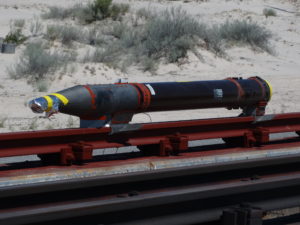
“But there are heat dissipation challenges that go with that, especially when something is operating at a very high data rate. You have to possess expertise in thermal management to solve those problems.”
Further compounding the heat challenge is that the amount of data being handled is expected to keep growing. “The data explosion is going to be uncontrollable. We’re working on 40GB/S links instead of the 20MB/S. The demand for data is so high that we will have to develop the technology to be very high speed. We will only be able to transmit at higher frequencies so we can transmit the data at a the wider bandwidths. It is a very exciting time.”
All of CWDS’ hypersonic FTI customers are doing short test flights, while studying the problem of how to collect the data from longer flights. Potential solutions include dedicated 5G links and laser-based satellite communications that link to the launch area. “The challenge is that the higher data rates will require higher
rate infrastructure,” says Cook.
“Contractors would rent time on those networks to gather their data. To give you an idea of the data rates – we size our systems to use 100GB interfaces to record the data they produce today.”
The missile market is growing quickly for CWDS, not just in hypersonics, but across all platforms as engineers redesign systems to reduce size, keep costs down and fly further. But there is also a lot of testing happening in space launch systems.
Cook says, “The commercial launch industry is ramping up just as fast as Hypersonics to support launches for high data rate satellites and to resupply the space stations – that market is also exploding. We are working with six launch companies at the moment,” he says.
“But the missile market will remain our predominant product during the next decade over flight test.”
Hypersonic flight may be an old idea, but it has new ambitions – and test facilities, instrumentation and data will play a major role in achieving them.
The psychological risks of a journey to Mars
One of the unknowns related to future missions to Mars is the length of the journey: the psychological consequences on the crew could compromise the success of a mission.
Among the most difficult aspects of any future missions to Mars there are certainly the considerable distance to cover and the isolation to which the crew would inevitably be subjected during the voyage. In recent years, several studies have tried to simulate the effects of such an experience on the psychology and dynamics of a potential group of astronauts, with effects that are not always predictable or encouraging.
WHY DO NOT YOU TALK TO ME? The latest of these experiments was conducted in Russia: the aim of the study was to verify the evolution of communications between the crew and mission control during a hypothetical journey of over 380 million kilometers.
Project SIRIUS (Scientific International Research In Unique terrestrial Station) this is the name of the experiment, involved two groups of 17 people who between 2019 and 2020 were locked up for 120 days in a structure that simulated the interior of a spacecraft traveling in deep space. The study results were published in Frontiers in Psychology.
GOODBYE PUNCTUALITY … Research has shown how the progressive delay in communications between the crew and the Earth, which increases as the distance traveled by the spacecraft, together with isolation, contribute to changing the interaction patterns between astronauts and ground mission control. From a practical point of view, the study showed how, with the passing of the days, the crew tends to be less punctual in reporting what happens on board and become progressively more autonomous in making decisions.
INDEPENDENT, BUT NOT TOO MUCH. While the fact that astronauts behave more and more like a team is positive in itself, it is quite worrying that, from mid-mission onwards, it considers it less and less important to consult mission control even in the most critical situations. This behavior, the researchers explain, risks compromising a future mission because it removes the control center from what happens on board. The study also confirmed the differences in behavior between men and women that had already emerged during other similar experiments.
MEN AND WOMEN. Psychologists have noted that women tend to be more precise and regular in their communications with the Earth, and also more likely to report problems. Men, on the other hand, focus more on “doing” and resolving any impasses without feeling compelled to make detailed reports as required by the procedures.ANOTHER ROUND. On November 4th a new SIRIUS mission “started”, with an expected duration of 8 months: who knows if the 17 volunteers will resist until the end …
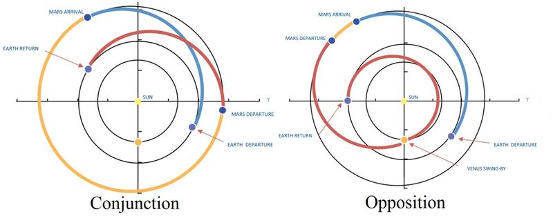
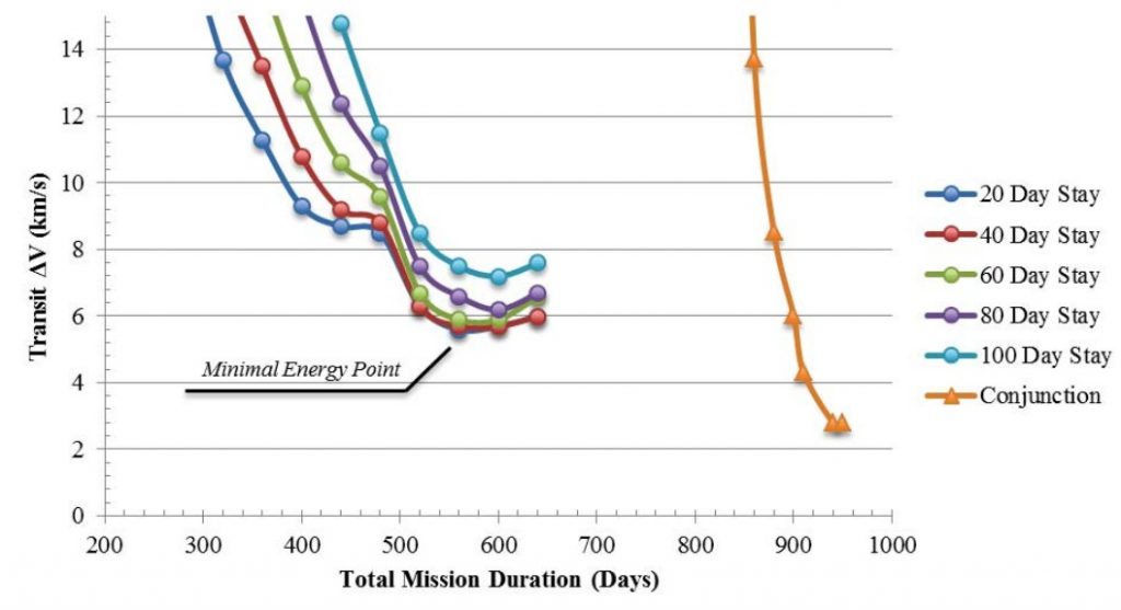
MARS MISSION DURATION. Manned missions to Mars split in two different types. They are named after astronomical names of the moments of departure of the ships from Mars: conjunction and opposition. Opposition type mission have less total time on Mars, but more time spent travel in weightless conditions, and a much higher radiation load. Conjunction mission have much more time spent in Mars surface. Сonjunction and opposite mission type examples:
| Mission type | Total mission duration, days | Earth-Mars trip, days | Time spent at destination | Mars-Earth trip, days | Total ∆V, km/s | Trans-Mars Injection, km/s | Mars Orbital Insertion, km/s | Trans-Earth Injection, km/s |
| Conjuction | 1005 | 198 | 558 | 197 | 2.81 | 0.5 | 1.25 | 1.06 |
| Opposition | 560 | 177 | 40 | 342 | 5.69 | 0.61 | 1.75 | 3.33 |
Namibia wants to become a green hydrogen superpower
According to the German Research Ministry, Namibia has the potential to produce renewable H2 for 1.5-2 euros per kilo, despite the additional cost of desalination of seawater required for electrolysis. Here are the strengths of a hydrogen hotspot.
Two thirds of the territory has solar irradiation values higher than 2,700 kWh / m2
In the run-up to the lowest price for green hydrogen there is a protagonist who is rarely talked about. When considering the countries in pole position to bring down the production costs of renewable H2, the thought usually goes to an economic power like Australia, which together with Japan is at the forefront of creating a global supply chain of green energy. Or to Chile, which has two tricks up its sleeve: the Acatama desert has the highest world solar radiation values, while Patagonia can count on winds among the most sustained and constant on the planet. On the other hand, we rarely think of Africa. Yet, there is a respectable contender: Namibia.
Low cost renewables
The southern African country has a mix of perfect conditions for obtaining energy from renewable sources at very low cost. It can count on over 3,500 hours of sunshine a year: to put it into perspective, the highest values of heliofania in Italy beat the 2,600 hours in Sardinia, Sicily, Calabria and Puglia.
In addition, two thirds of its territory have solar irradiation values higher than 2,700 kWh / m2, similar to those of Australia and higher than those of much of the Arabian Peninsula. Furthermore, a large part of the coastal areas of Namibia have ideal conditions for wind farms.

A green hydrogen superpower?
These assumptions make Namibia a paradise for the production of green hydrogen. According to Stefan Kaufmann, Commissioner for Innovation for Green Hydrogen at the German Ministry of Education and Research, the cost of a kilo of H2 in the country could easily be between 1.5 and 2 euros. These price levels already incorporate the surplus necessary for the desalination of sea water with which to feed the electrolysis. The process, in fact, uses technology based on platinum and iridium, both metals with which the country is well supplied. On balance, desalination should only affect 1% of the final production cost.
However, this potential has not been exploited so far. HYPHEN Hydrogen Energy will be the first to think about it, which in November 2021 was awarded a project worth 9.6 billion dollars (equal to the country’s annual GDP), 3GW of electrolysis capacity and 5GW of installed capacity between wind and solar power. Annual production is expected to reach 300,000 tons of green hydrogen.
The project will be located in a strategic area, in the Tsau Khaeb national park, in the desert 100 km from the coast, very close to the main naval routes and major land corridors in southern Africa. The country plans to start exporting the energy carrier in 2025. Obviously, once the necessary infrastructures are completed, especially the port ones. For which the Windhoek government wants to focus on public-private partnerships and is already catalyzing the interest of investors. Taking advantage of another factor that should not be underestimated: Namibia is among the least corrupt countries in sub-Saharan Africa, according to the ranking of Transparency International.
James Webb Space Telescope Is Successfully Stretching Its Sunshield
After multiple setbacks, the telescope is back on track
After near 30 years of planning and thorough work, NASA finally launched its long-awaited $10 billion next-gen space observatory, the James Webb Space Telescope on December 25. Following its launch, the telescope has started unfurling into its final shape.
Since they were massive at more than 21 feet (6.5 m) across, the telescope’s sunshield and primary mirror had to be folded to fit into the European Ariane rocket it launched on. And the riskiest part of the process was the tightening of that massive sunshade.
While the operation was initially smooth sailing, the team behind James Webb Space Telescope encountered some problems during the deployment of the sunshade. Even though Hubble’s successor was never really in grave danger owing to its constant power flow, the deployment was considered to be the project’s most challenging hurdle. First, the flight controllers in Maryland had to reset Webb’s solar panel to draw more power, then they also had to repoint the telescope to prevent any kind of overheating on its motors by limiting sunlight.
After the motors were cooled down and it was safe to continue, the team re-started a three-day process of stretching the tennis court-sized sunshield on the James Webb Space Telescope. According to the officials, it is now in the process of being fully stretched and should be ready by Wednesday, January 5.
What makes the sunshield so crucial for the telescope is its ability to cool down James Webb Space Telescope’s enormous mirror and infrared instruments to nearly 400 degrees below zero and block out the heat of the sun while they explore the universe and the atmospheres of alien worlds for possible signs of life.
If all goes according to plan, Webb should be able to reach its final destination of 1 million miles (1.6 million kilometers) away from the earth by the end of this month. As of January 3, the telescope is already halfway there. By the end of June, the massive observatory should begin exploring the universe, hopefully unveiling the mysteries behind the very first stars and galaxies formed in the universe 13.7 billion years ago.
Features
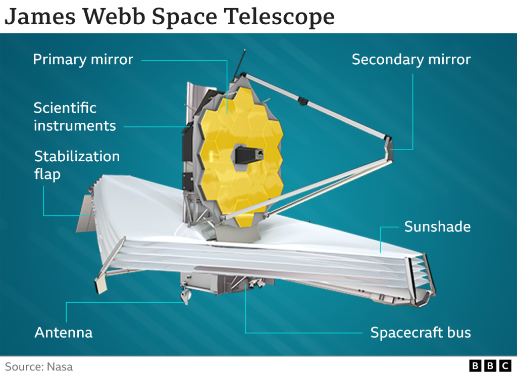
The James Webb Space Telescope has a mass about half of Hubble Space Telescope‘s, but a 6.5 m (21 ft)-diameter gold-coated beryllium primary mirror made of 18 hexagonal mirrors, giving it a total size over six times as large as Hubble’s 2.4 m (7 ft 10 in). Of this, 0.9 m2 (9.7 sq ft) is obscured by the secondary support struts, making its actual light collecting area about 5.6 times larger than Hubble’s 4.525 m (14.85 ft) collecting area.
JWST is designed primarily for near-infrared astronomy, but can also see orange and red visible light, as well as the mid-infrared region, depending on the instrument. The design emphasizes the near to mid-infrared for three main reasons:
high-redshift objects have their visible emissions shifted into the infrared cold objects such as debris disks and planets emit most strongly in the infrared this band is difficult to study from the ground or by existing space telescopes such as Hubble Ground-based telescopes must look through Earth’s atmosphere, which is opaque in many infrared bands (see figure of atmospheric absorption). Even where the atmosphere is transparent, many of the target chemical compounds, such as water, carbon dioxide, and methane, also exist in the Earth’s atmosphere, vastly complicating analysis. Existing space telescopes such as Hubble cannot study these bands since their mirrors are insufficiently cool (the Hubble mirror is maintained at about 15 °C (288 K; 59 °F)) thus the telescope itself radiates strongly in the infrared bands.[37]
JWST will operate in a halo orbit around the Sun-Earth L2 (Lagrange point), approximately 1,500,000 km (930,000 mi) beyond Earth’s orbit around the Sun. By way of comparison, Hubble orbits 550 km (340 mi) above Earth’s surface, and the Moon is roughly 400,000 km (250,000 mi) from Earth. This distance probably makes it impossible for a crewed mission to repair or upgrade the observatory in the future, as was done for Hubble. During the long JWST testing period, NASA officials referred to the idea of a servicing mission, but no plans were announced.[39][40]
Objects near this Sun-Earth L2 point can orbit the Sun in synchrony with the Earth, allowing the telescope to remain at a roughly constant distance with continuous orientation of its unique sunshield and equipment bus toward the Sun, Earth and Moon to simultaneously block heat and light from all of these, and also to maintain communications. This arrangement will keep the temperature of the spacecraft below the 50 K (−223 °C; −370 °F) necessary for faint infrared observations.