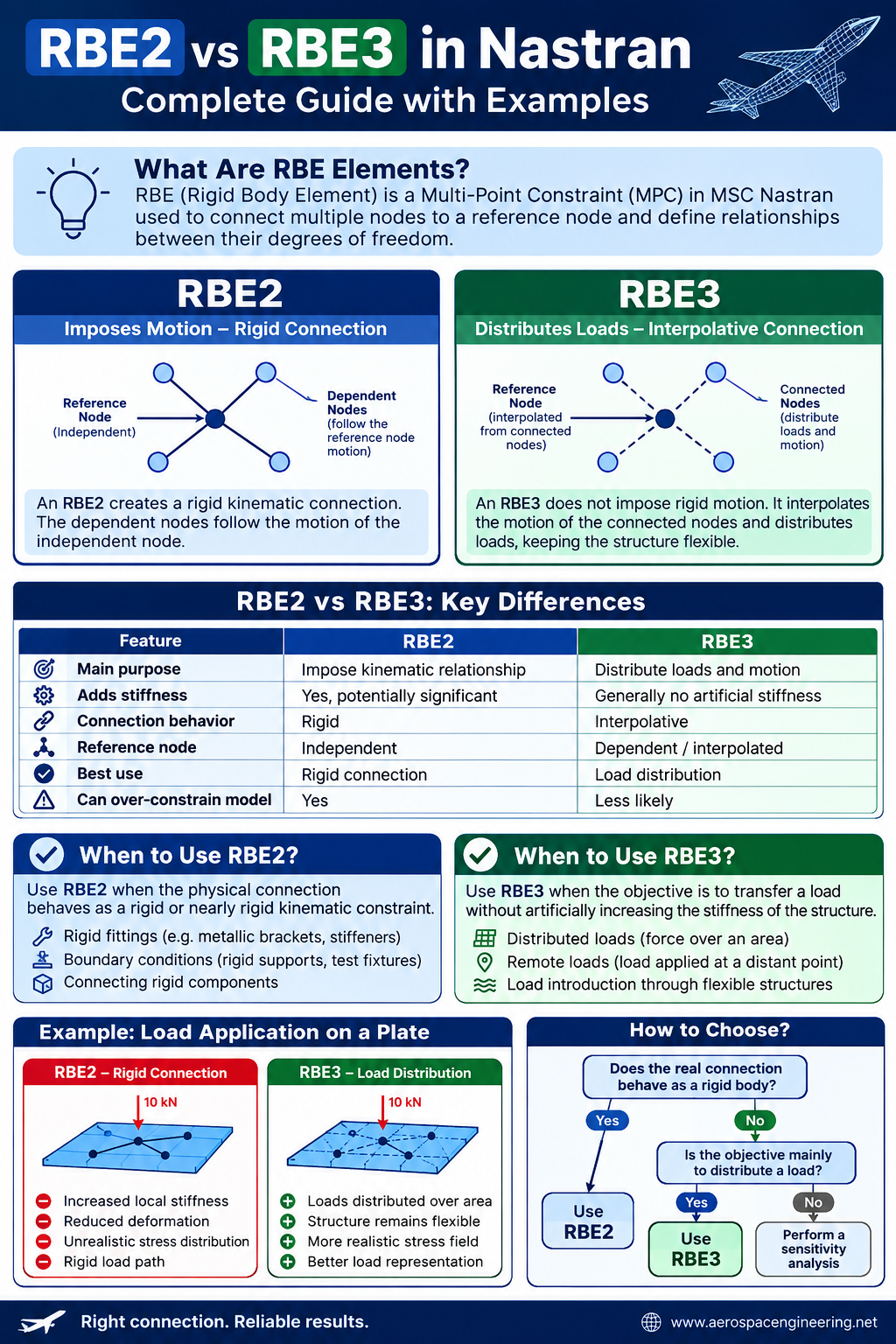
Finite Element Analysis is only as good as the way loads, constraints, and connections are represented. In MSC Nastran, two of the most widely used elements for connecting parts of a finite element model are RBE2 and RBE3.
At first glance, they may appear similar. Both connect multiple nodes to a reference node. However, their mechanical behavior is fundamentally different.
Using the wrong one can:
- artificially increase the stiffness of a structure;
- create unrealistic load paths;
- generate misleading stress concentrations;
- distribute loads incorrectly;
- affect modal and buckling results.
This guide explains the difference between RBE2 and RBE3, when to use each one, and the most common modeling mistakes.
What Is an RBE Element?
RBE stands for Rigid Body Element. In Nastran, RBE elements are Multi-Point Constraints (MPCs) used to define relationships between degrees of freedom of different nodes.
The most common rigid elements are:
- RBE2
- RBE3
Although both involve a reference node and several connected nodes, they solve completely different modeling problems.
The simplest way to remember the difference is:
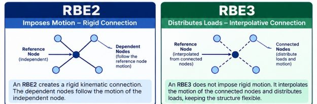
RBE2 imposes motion. RBE3 distributes load.
That single concept is the foundation for understanding when each element should be used.
1. What Is an RBE2?
An RBE2 element creates a rigid kinematic connection between one independent node and one or more dependent nodes.
The motion of the dependent nodes is constrained by the motion of the independent node.
In simplified form:
Dependent node displacement = motion imposed by the independent node
If the independent node translates, the connected nodes follow that motion.
If the independent node rotates, the connected nodes move according to a rigid-body relationship.
This means that an RBE2 introduces a rigid connection between the selected degrees of freedom.
Basic RBE2 Configuration
An RBE2 typically contains:
- one independent node;
- multiple dependent nodes;
- selected degrees of freedom.
For example, an RBE2 may connect a central reference node to the nodes around a circular hole.
If all six degrees of freedom are selected:
- translations: 1, 2, 3;
- rotations: 4, 5, 6.
the connected region behaves as if it were connected to a rigid structure.
RBE2 Example: Applying a Load Through a Bolt Hole
Imagine a plate with a circular hole.
You want to apply a force through the center of the hole.
A simple model could look like this:
           o   o
        o         o

            ●
         Reference
            Node

        o         o
           o   o
The nodes around the hole are connected to the central reference node using an RBE2.
A force can then be applied at the central node.
The RBE2 transfers the motion and load through the connected nodes.
This can be useful when the real structure is connected to a component that is significantly stiffer than the surrounding structure.
For example:
- rigid brackets;
- stiff fittings;
- idealized joints;
- actuators;
- test fixtures.
However, there is an important risk.
The RBE2 may make the surrounding structure artificially stiff.
2. What Is an RBE3?
An RBE3 element does not create a rigid connection between the reference node and the connected nodes.
Instead, it creates an interpolation relationship.
The motion of the reference node is calculated as a weighted average of the motion of the connected nodes.
Conceptually:
Reference Node Motion
          ↓
Calculated from
          ↓
Weighted Motion of Connected Nodes
This means that an RBE3 generally distributes loads without imposing significant artificial stiffness on the connected structure.
That is why RBE3 elements are extremely useful when loads must be distributed over an area.
The Most Important Concept
With an RBE3:
The connected structure remains flexible.
The RBE3 transfers forces and moments according to the specified interpolation and weighting.
Unlike an RBE2, it does not force the connected nodes to behave like part of a rigid body.
3. RBE2 vs RBE3: The Fundamental Difference
The difference can be summarized as follows:
| Feature | RBE2 | RBE3 |
|---|---|---|
| Main purpose | Impose kinematic relationship | Distribute loads and motion |
| Adds stiffness | Yes, potentially significant | Generally no artificial stiffness |
| Connection behavior | Rigid | Interpolative |
| Reference node | Independent | Dependent/interpolated |
| Best use | Rigid connection | Load distribution |
| Can over-constrain model | Yes | Less likely |
| Suitable for distributed loads | Sometimes | Excellent |
| Suitable for rigid fittings | Excellent | Usually not appropriate |
The key difference is therefore:
RBE2 controls displacement.
RBE3 calculates displacement and distributes loads.
4. Example: Applying a Force to a Circular Area
Consider a 10 kN force applied to the center of a circular plate.
There are two possible approaches.
Case A: Using an RBE2
The central node is connected to the surrounding nodes using an RBE2.
              10 kN
                ↓
                ●
             RBE2 Node
            /  |  \
          o----o----o
         /           \
        o             o
The nodes connected to the RBE2 are forced to follow the rigid-body motion of the reference node.
The result may be:
- reduced local deformation;
- increased stiffness;
- altered stress distribution;
- unrealistic load path if the actual load introduction mechanism is flexible.
The model may look perfectly stable and produce apparently reasonable stresses.
However, the physical behavior may be incorrect.
Case B: Using an RBE3
Now the same 10 kN load is applied to a reference node connected through an RBE3.
              10 kN
                ↓
                ●
             RBE3 Node
            /  |  \
          o    o    o
         /           \
        o             o
The force is distributed among the connected nodes.
The plate remains free to deform according to its actual stiffness.
The resulting stress and displacement field is generally more representative of a distributed load introduction.
For this reason, RBE3 is often the preferred choice for:
- distributed forces;
- aerodynamic loads;
- pressure load idealization;
- inertia load transfer;
- remote loads;
- actuator load introduction.
5. When Should You Use RBE2?
An RBE2 should be used when the physical connection is intended to behave as a rigid or nearly rigid kinematic constraint.
Typical applications include:
Rigid fittings
If a metallic fitting is significantly stiffer than the connected structure, an RBE2 may be an appropriate idealization.
For example:
Flexible Structure
       │
       │
   [ RBE2 ]
       │
       ●
   Reference Node
The RBE2 represents the stiff connection.
Boundary Conditions
RBE2 elements can also be used to connect a group of nodes to a reference node where boundary conditions are applied.
For example:
- test fixtures;
- rigid supports;
- simplified interfaces;
- idealized mounting points.
Care must be taken to avoid creating unrealistic stiffness.
Connecting Rigid Components
If a component is known to be much stiffer than the surrounding structure, representing the connection using an RBE2 may be computationally efficient.
However, the assumption should always be verified.
A component that appears rigid in reality may still introduce local flexibility that is important for:
- stress analysis;
- fatigue;
- vibration;
- buckling.
6. When Should You Use RBE3?
An RBE3 is usually the better choice when the objective is to transfer a load without artificially increasing the stiffness of the structure.
Typical applications include:
Distributed Loads
Suppose a force must be applied over a structural interface.
Instead of applying the entire force to one node, an RBE3 can distribute the force among multiple nodes.
This reduces unrealistic local stress concentrations.
Remote Loads
A remote force may be defined at a reference point located away from the structure.
For example:
      Load Application Point
              ●
              │
              │
             RBE3
          /    |    \
         o     o     o
The load is transferred to the structure while allowing the connected nodes to deform naturally.
Load Introduction Through Flexible Structures
An RBE3 is particularly useful when the actual load introduction mechanism is not perfectly rigid.
Examples include:
- aerodynamic pressure resultants;
- distributed mechanical loads;
- interfaces represented by multiple structural nodes;
- simplified connection regions.
7. The Artificial Stiffness Problem
One of the most common FEM modeling mistakes is using an RBE2 where an RBE3 should have been used.
Consider a flexible plate.
If an RBE2 connects a large group of nodes to a central node, the connected region may behave like a rigid body.
The local flexibility of the plate is reduced.
This can affect:
- displacement;
- stress distribution;
- natural frequencies;
- buckling load;
- load path.
The effect becomes particularly significant when the RBE2 connects nodes over a large area.
A large RBE2 spider can effectively create a rigid plate inside a flexible structure.
This is often physically unrealistic.
8. The “Rigid Spider” Effect
A common modeling technique is to create a spider connection.
For example:
        o       o
          \   /
            ●
          /   \
        o       o
The central node is connected to surrounding nodes.
If an RBE2 is used, the spider behaves rigidly.
If the same configuration uses an RBE3, the structure remains flexible.
This distinction is critical.
A useful rule is:
If the spider is only required to distribute a load, start by considering RBE3.
If the spider represents a genuinely rigid connection, RBE2 may be appropriate.
9. Load Distribution with RBE3 Weighting Factors
RBE3 elements can use weighting factors to control how loads are distributed among connected nodes.
For example, assume four nodes:
Node A → Weight 1
Node B → Weight 1
Node C → Weight 2
Node D → Weight 2
Nodes C and D will have a greater contribution to the interpolation.
Weighting can be useful when the load should not be distributed uniformly.
For example:
- different structural areas;
- different stiffness regions;
- asymmetric load paths;
- aerodynamic resultant locations.
However, weighting should not be used arbitrarily.
The weighting strategy should represent a physically meaningful load distribution.
10. RBE2 and RBE3 in Modal Analysis
Rigid elements can have a significant influence on modal analysis.
RBE2
An RBE2 can increase the effective stiffness of the model.
As a result, natural frequencies may increase.
The effect depends on:
- number of connected nodes;
- size of the connection;
- selected degrees of freedom;
- flexibility of the surrounding structure.
A large RBE2 in a flexible structure can significantly alter the mode shapes.
RBE3
An RBE3 generally allows the connected structure to retain its flexibility.
Therefore, it is often preferable when a load or mass must be distributed without creating an artificial rigid region.
However, the complete dynamic model must still be checked carefully.
For modal analysis, always verify:
- rigid body modes;
- connectivity;
- mass distribution;
- constraints;
- mode shapes.
11. RBE2 and RBE3 in Buckling Analysis
The choice between RBE2 and RBE3 can also affect buckling results.
Consider a thin panel subjected to compression.
If an RBE2 artificially stiffens the load introduction region, the predicted buckling load may be higher than the real value.
The model may show:
RBE2 → Increased Local Stiffness
      ↓
Higher Predicted Buckling Load
      ↓
Potentially Non-Conservative Result
Using an RBE3 may provide a more realistic load distribution while allowing the structure to deform.
For buckling analysis, always compare:
- RBE2 vs RBE3 results;
- displacement field;
- stress distribution;
- eigenvectors;
- local deformation near the connection.
A sensitivity study can reveal whether the modeling choice significantly affects the results.
12. Common Mistakes When Using RBE2
Mistake 1: Connecting Too Large an Area
A large RBE2 spider can create an unrealistic rigid zone.
Better approach
Use:
- a smaller connection area;
- RBE3 for load distribution;
- a detailed connection model;
- flexible elements.
Mistake 2: Constraining Too Many Degrees of Freedom
It is not always necessary to connect all six degrees of freedom.
For shell models, the selected DOFs should reflect the actual physical connection.
For example, connecting rotations unnecessarily may introduce unrealistic constraints.
Always ask:
Which motion is actually transferred by the real component?
Mistake 3: Ignoring the Load Path
An RBE2 may create a load path that does not exist in the real structure.
The model can transfer forces through a rigid mechanism that would actually deform significantly.
Always examine:
- where the force enters the structure;
- which components transfer the load;
- which regions are flexible;
- which interfaces are actually rigid.
13. Common Mistakes When Using RBE3
Mistake 1: Using RBE3 as a Physical Rigid Connection
An RBE3 should not be used when the objective is to enforce rigid-body motion.
If a component must move rigidly, an RBE2 or another appropriate connection method may be required.
Mistake 2: Incorrect Weighting
Weight factors can significantly affect the load distribution.
Incorrect weights may create:
- unrealistic forces;
- unexpected moments;
- asymmetric load transfer.
The weighting should be based on geometry or physical load distribution whenever possible.
Mistake 3: Ignoring Rotational Degrees of Freedom
The selected DOFs must match the modeling objective.
A poorly defined RBE3 can transfer loads in an unexpected way.
Always inspect:
- SPC forces;
- MPC forces;
- reaction forces;
- equilibrium.
14. How to Choose Between RBE2 and RBE3
Use this simple decision process.
Question 1
Does the real connection behave as a rigid body?
If yes:
→ Consider RBE2.
If no:
→ Continue.
Question 2
Is the objective mainly to distribute a load across multiple nodes?
If yes:
→ Consider RBE3.
Question 3
Would an artificial rigid zone affect the results?
If yes:
→ Prefer RBE3 or a more realistic connection model.
Question 4
Are you analyzing local stress, buckling, or modal behavior?
If yes:
→ Perform a sensitivity analysis because the choice of rigid element may significantly affect the results.
15. RBE2 vs RBE3: Practical Decision Table
| Modeling Situation | Recommended Approach |
|---|---|
| Rigid fixture | RBE2 |
| Very stiff fitting | RBE2 |
| Distributed force | RBE3 |
| Remote load | RBE3 |
| Load applied over flexible area | RBE3 |
| Idealized rigid interface | RBE2 |
| Modal analysis load distribution | Usually RBE3 |
| Buckling load introduction | Often RBE3, verify sensitivity |
| Bolt hole load introduction | Depends on joint stiffness |
| Test fixture connection | Often RBE2 |
| Flexible mechanical interface | RBE3 or detailed model |
16. A Practical Workflow for Aerospace FEM Models
Before creating an RBE element, follow this process.
Step 1: Understand the physical connection
Ask:
- Is the connection rigid?
- Is it flexible?
- Does it transmit moments?
- Does it allow rotation?
- Is the load concentrated or distributed?
Step 2: Define the modeling objective
Are you evaluating:
- global displacement?
- local stress?
- fatigue?
- buckling?
- modal response?
The required modeling fidelity may change.
Step 3: Select the connection method
Choose between:
- RBE2;
- RBE3;
- CBUSH;
- CELAS;
- MPC;
- detailed solid or shell connection.
Step 4: Verify the load path
Check:
- SPC forces;
- free body equilibrium;
- force balance;
- deformation pattern.
Step 5: Perform a sensitivity study
When results are important, compare alternative connection methods.
For example:
Model A → RBE2
Model B → RBE3
Model C → Flexible connection
Compare:
- displacement;
- stress;
- reaction forces;
- natural frequencies;
- buckling factors.
If the results change significantly, the connection modeling assumption is important and should be investigated further.
Frequently Asked Questions
Does RBE2 increase stiffness?
Yes. An RBE2 imposes rigid kinematic relationships between nodes and can significantly increase the local or global stiffness of a finite element model.
The effect depends on the geometry, connected degrees of freedom, and flexibility of the surrounding structure.
Does RBE3 add stiffness?
An RBE3 is generally used to distribute loads and interpolate motion without creating the same artificial rigid region associated with an RBE2.
However, the complete constraint system must always be checked to ensure that the model behaves as intended.
Can RBE2 and RBE3 be used together?
Yes.
In complex models, an RBE2 may represent a rigid component while an RBE3 distributes a load from another interface.
The important point is to avoid creating conflicting constraints or unrealistic load paths.
Which one is better for applying a force?
If the force must be distributed over a flexible structure, an RBE3 is usually the preferred option.
If the force is transmitted through a genuinely rigid component, an RBE2 may be more appropriate.
Is RBE2 always wrong for bolt holes?
No.
The correct choice depends on the physical joint.
A rigid bolt or fitting may justify an RBE2 approximation for some global analyses.
For local stress, bearing loads, joint flexibility, or fatigue analysis, a more detailed representation may be necessary.
Conclusion
RBE2 and RBE3 elements are among the most powerful and frequently misunderstood modeling tools in MSC Nastran.
The difference is simple but fundamental:
RBE2 imposes a rigid kinematic relationship.
RBE3 distributes loads and interpolates motion without imposing the same rigid behavior.
An RBE2 is appropriate when the physical connection is genuinely rigid or when a rigid constraint is intentionally required.
An RBE3 is generally more appropriate when a load must be distributed across a flexible structure without artificially increasing its stiffness.
The best practice is not to choose an RBE element based on habit.
Instead, start from the real physical behavior, identify the expected load path, and verify the modeling assumption through sensitivity analysis.
In aerospace structural analysis, a seemingly small modeling decision—such as choosing RBE2 instead of RBE3—can influence stress, displacement, natural frequencies, and buckling results.
For that reason, the question should never simply be:
“Which element should I use?”
The real question is:
“What physical behavior am I trying to reproduce?”
If you answer that correctly, choosing between RBE2 and RBE3 becomes much easier.