Improvement of joints with rows of bolts or rivets
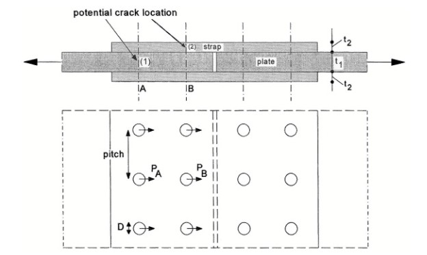
A simple double strap joint with two rows of bolts at each side of the joint is shown in the following Figure.
It could be a good design from a static point of view if both rows carry the same load because then PA = PB which implies the same bearing pressure on the hole and the same shear stress in the bolts. This is possible if the sum of the thicknesses of the two straps is equal to the thickness of the plates: 2t2 = t1. However, from a fatigue point of view, this design is not the best one. The holes in row B of the plate are loaded by PB only. In row A, the same load PA is present on the holes, but the load already introduced in row B is also passing these holes (bypass load).
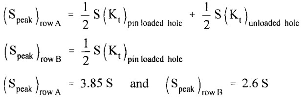
The first formula shown above is the peak stress at the hole in row A. S is the nominal net section stress in the plate. Kt is the stress concentration factor.The second term is from the bypass load. The second formula is the peak stress for row B. For a ratio of hole diameter to hole pitch of 1/5, the Kt-values of a pin loaded hole and an unloaded hole are 5.2 and 2.5 respectively. The results shown in the third row, are an approximation because for Kt of the bypass load (unloaded hole) it has been assumed that the hole is an open hole whereas a bolt is present in the hole, and the Kt-values do not consider fretting corrosion in the hole. The holes in the plate in row A are more severely loaded than the holes in row B and thus will be more fatigue critical. For the straps, the reverse
is true for the same reasons. Fatigue cracks occur at either location (1) or (2) in Figure 1. Cracks in the plate (location 1) are invisible, it may cause an inspection problem.
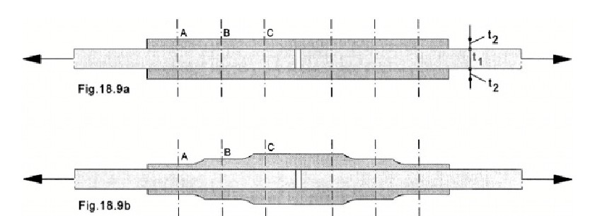
Two butt joints with three rows of bolts are shown in Figure 2, one joint with a constant thickness of the strap plates, and a second one having strap plates with a staggered thickness. The distribution of the load transmission between the three rows can be obtained by a simple elastic calculation considering equal displacements of bolt holes in the plate and the Straps. The result of the simple displacement compatibility analysis is that PA = PC and PB = 0; in other words, the middle row of bolts does not contribute to load transmission. his can easily be understood by considering that the strain between A and C is constant and equal in the plate and the two straps.
It implies that the displacements of the holes at B in the plate and in the straps are equal and thus the bolts in row B remain unloaded. A more elaborate FE calculation will indicate that the bolts of the second row carry some load, but still much less than the bolts in the other two rows. Under static load until failure, the bolts in row B will significantly contribute to load transmission because plastic deformation around the holes will lead to a more homogeneous load distribution between the three rows.
A better distribution of load transmission between the three rows is obtained by staggering the thickness of the straps, see Figure 2b. This can be done in such a way that PA = PB = PC. The distribution of the load transmission between the three rows can be obtained by a simple elastic calculation considering equal displacements of bolt holes in the plate and the straps. he end-row effect on fatigue can be reduced by designing the staggered strap for a lower load transmission than 1/3. Such improvements are obtained by local variations of the stiffness of the joint.
Clamping bolts of a joint/ Bolts loaded in tension
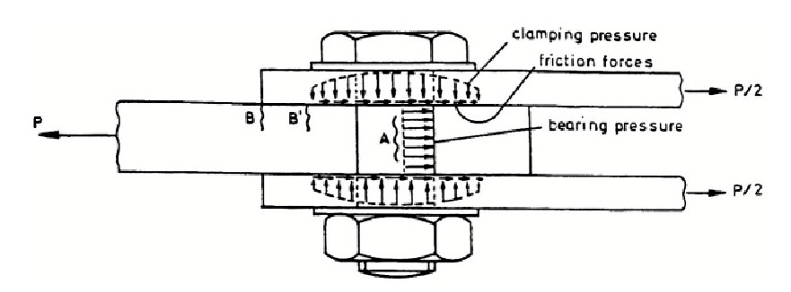
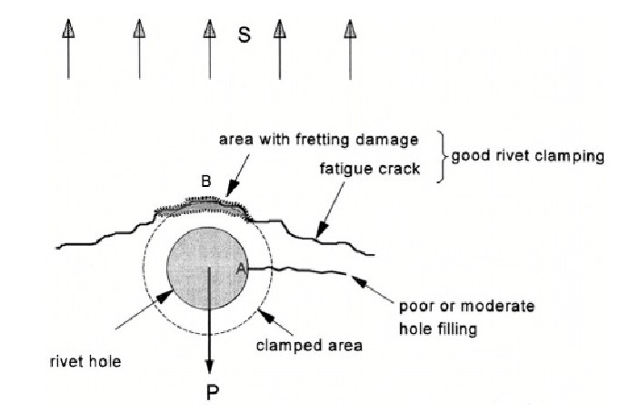
Bolts can be pre-tensioned by controlled torque with a torque wrench. This can have a large impact on the fatigue life. Load transfer from one element to another one now occurs partly by frictional forces. Moreover, the coefficient of friction, which statically may be in the order of 0.3 for a dry assembling, can increase considerably under cyclic load as a result of fretting between the clamped plates. If clamping is absent, fatigue cracks are initiated at the edge of the hole in the net section, see location A in Figure 3. However, after sufficient tightening of the bolt, fretting movements inside the hole are suppressed. Crack initiation shifts to locations B or B`. Clamping will increase the fatigue strength until this shift of the crack location has occurred. More clamping should not give a further improvement.
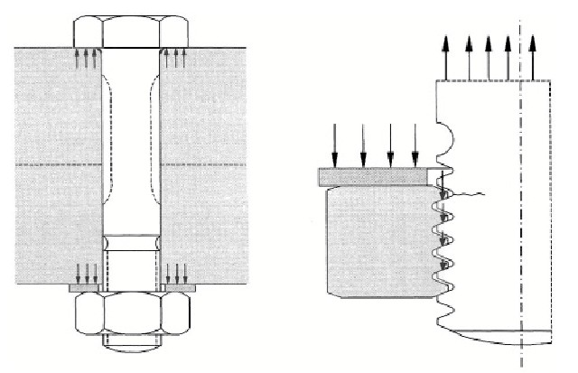
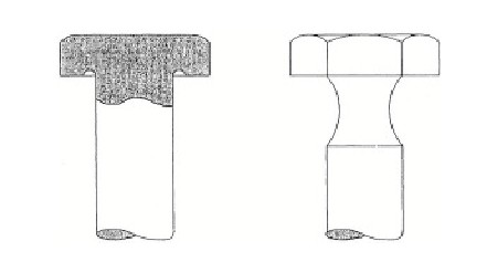
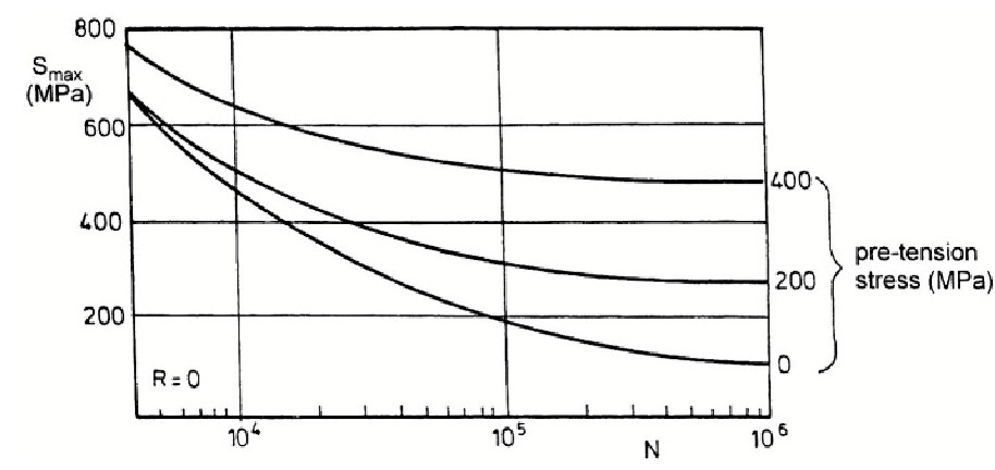
As indicated in Figure 4 by the arrows on the screw threads, the largest contribution to the load transmission occurs by the first full screw thread of the nut. As a result, fatigue cracks initiate at the corresponding screw thread of the bolt, the more so because the loads of the other screw threads also pass through this cross section (bypass load). Most fatigue failures occur at this location of the bolt. Two possibilities to reduce the root radius between the bolt head and shank are shown in Figure 5. The local Kt-value can thus be reduced. Improved screw thread concepts for bolts and nuts were also proposed. However, special bolts and nuts are not generally appreciated to avoid fatigue problems. Designers prefer to rely on high-quality bolts and pre-tensioning the bolt. High quality bolts are made of low-alloy steel which allows a high pre-tension in the bolt. The improvments due the pretension effect on the S-N curve is shown in the figure below. It is for a steel bolt loaded in tension (diameter 10 mm).
The favorable effect of a high squeeze force (riveting force) on the fatigue life of the rivets is shown by Figure 6. An increased squeezing force will also increase the clamping force of the rivets on the sheets. Clamping of the rivets affects the location of the fatigue crack. If the clamping is poor, cracks start at the rivet holes in the minimum section of the most critical end row, i.e. at point A in Figure 7. Fretting at that location causes crack initiation. However, if an improved clamping is obtained, fretting movements are no longer possible near the hole. Crack nucleation starts still in the minimum section by fretting between the two mating surfaces, but it occurs slightly outside the hole, see the semi-elliptical cracks in Figure 7.
Improvement of the fatigue limit of a lug
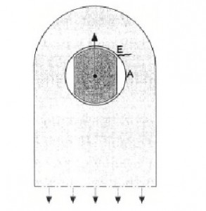
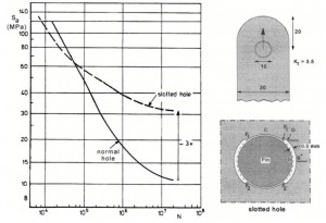
The fatigue limit of a lug is very low, in addition to a relatively high stress concentration factor, the low fatigue limit is primarily due to fretting corrosion in the hole. The fatigue limit of a lug can be improved in two different ways: prevention of fretting corrosion, and reduction of the detrimental effect of fretting corrosion damage by introducing compressive residual stresses. Fretting corrosion is most effectively eliminated by preventing contact between the pin or bolt and the bore of the hole. This can be achieved by slotted holes as shown in the following figures.
The results in Figure 9 show that a most impressive improvement of the fatigue limit was obtained. Unfortunately, slotted holes are “expensive” holes. To avoid the metallic contact at points A in (Figure 8), by using pins with flat sides. It was observed that cracks in lugs with pins with flat sides started at point E (Figure 8). The cracks were still initiated by fretting corrosion, but at a location where the tangential stress is lower than at point A, and the fretting movements are smaller.
Another method for preventing fretting corrosion is by using an interference fit between the pin and lug hole. Assembling and disassembling of such a joint is no longer feasible. However, a bushing pressed into a lug hole is a good alternative. This should be done with a high interference fit in order to prevent fretting movements between the bushing and bore of the hole. hole. The interference fit introduces a high tangential compression stress in the bushing, which suppresses fatigue in the bushing itself. Morever, the hole in the lug is protected against handling damage caused by mounting and dismounting bolts or pins.
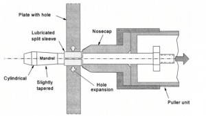
The fatigue limit can be increased considerably with a plastic hole expansion, it can occur by pulling an oversized mandrel through the hole. Two methods were developed for this purpose. The first one is the split-sleeve expansion method developed in the 1970’s. The method is illustrated by Figure 10.
A mandrel is moved through the hole, and then the split sleeve (a bushing with a single split) is moved along the mandrel into the hole. Retraction of the mandrel through the hole and the sleeve in the hole requires a radial expansion of the sleeve and the hole together. As a result, the diameter of the hole is increased by plastic deformation around the hole, and compressive residual stresses in the tangential direction will remain afterwards.
A large force is necessary for retraction of the mandrel, but the sleeve has a split and thus the sleeve can easily expand by a small opening of the slit. Furthermore, the friction between the mandrel and the sleeve is reduced by a surface coating baked on the inside of the sleeve. After the mandrel has been retracted, the hole is reamed to the final size and a correct cylindrical shape.
The second technique, developed in the 1990’s is the split-mandrel method, A mandrel is used with two mutually perpendicular slits along a large part of the mandrel, see Figure 11. The maximum diameter is larger than the hole diameter, but the mandrel can still pass through the hole because the slits can be closed by some elastic bending of the four quadrants of the mandrel. Before retracting the mandrel, a pin is inserted in the center of the mandrel. This prevents closure of the slits during the retraction. The frictional forces between the mandrel and the bore of the hole are reduced by a lubricating oil.
Plastic hole expansion has been successfully applied to many aircraft structures. It is also an attractive method for repair if small cracks occur in service at bolt holes. The bolt is removed, the hole is cleaned and reamed, the hole is plastically expanded and a new bolt with a slightly larger diameter is installed. An expansion by 2 to 3% is typical which is sufficient to obtain a significant improvement of the fatigue strength.
