An Overview of Drones and their Applications
Drones are becoming more reliable, faster, accurate, and stable, with industries developing platforms for commercial use. Autonomous capabilities offer opportunities for rescue, emergency supplies, and combat operations.
What is a drone?
Drones, also known as unmanned aerial vehicles (UAVs), are flying robots controlled remotely or autonomously using software-controlled flight plans. Initially used for military purposes, they now serve civilian roles such as intelligence gathering, anti-aircraft target practice, and weapons platforms. They work with onboard sensors and GPS.
Drones are now also used in a range of civilian roles, including the following:
- search and rescue
- surveillance
- traffic monitoring
- weather monitoring
- firefighting
- personal use
- drone-based photography
- videography
- agriculture
- delivery services
What is Drone Technology?
A drone is a flying robot that can be operated manually or autonomously using sensors. They have four rotors, usually a quadcopter design, which generate thrust against Earth’s gravitational force. If the thrust equals the drone’s weight, it hovers, and if it’s higher or lower than the force, it climbs or descends in the air.
The thrust generated by the propellers is given by:

where D (m) is the diameter of the propeller, ρ (Kg/m3) is the density of air (1.225 kg/ m3), v(m/s) is the velocity of air at the propeller, and Δν (m/s) is the velocity of air accelerated by the propeller.
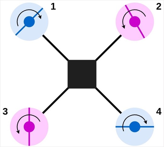
The thrust generated is vertically opposite to the direction of gravity and thus, the drone’s height can only ascend or descend in place unless it has a component of generated thrust in other directions as well. One set of diametrically opposite rotors rotates clockwise, while the other set rotates counter-clockwise. If they have the same rotational speeds, both sets cancel out the reactive yaw generated, and thus, the drone can only translate. By varying the speed of rotation of the propellers, the drone’s pitch and roll can be controlled.
Note: To move ahead in a particular direction, the drone needs to have its nose down such that the thrust has a component in the horizontal plane (see figure below).
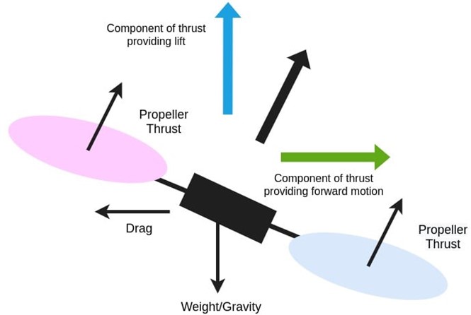
Physics Behind Drone Motion
A drone’s motion is influenced by the rotation of its propellers and the thrust generated against gravity and in the horizontal plane.
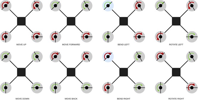
The scenarios for drone motion are:
- If all propellers rotate fast, the drone rises up against the gravity and vice versa
- If the rear propellers rotate faster, the nose pitches down and the drone generates a component of thrust in the forward direction for the forward motion of the drone and vice-versa
- If the right side propellers rotate faster, they generate thrust for roll control, allowing the drone to move to the left and vice-versa
- If the right diagonal propellers rotate faster, they generate yaw force due to a reactive force that obtains yaw control, allowing the drone to rotate left and vice-versa
How It’s Made
Since drones generate a lot of thrust to battle strong winds, air resistance, and particles in the air, they need a strong body. They also need to absorb vibrations while being lightweight to reduce the load the drone body needs to lift against the gravitational force. Lightweight drones are also more agile and can react faster due to less inertia.

Most commercial drones have a lightweight carbon fiber body with a honeycomb design for the limbs that hold the rotors. The brushless motors on these drones can rotate at more than 10000 RPM and generate enough thrust to lift up the body weight. The embedded control unit, usually a microcontroller with multiple sensors, is mounted on top of the drone while the battery is placed below the controller. The battery is usually the drone’s heaviest component.
What Electronics Are in a Drone?
The most important components on a drone include a microcontroller board that runs the computations for the control of the motors, the motor speed control components, sensors for various measurements, and the drone’s lifeline, the battery.
A flight controller for a drone is a common microcontroller, but usually with high processing speed and a bare minimum of sensors onboard, needed for stabilizations. The most common commercially available flight controllers for drones are PixHawk 4, Navio2, and Beaglebone Blue capable of running the ArduPilot and PX4 autopilot software.
A 3D gyroscope is usually needed to at least have the ability to automatically stabilize the drone on a horizontal plane.
The sensor suite of a drone can include:
- Gyroscope: provides the angular velocity of the drone and thus its orientation in the 3D world
- Accelerometer: measures the linear acceleration but mainly used to know the direction of gravity
- Magnetometer: detects the Earth’s magnetic field and obtains the drone’s compass direction
- Barometer: detects the pressure and indirectly computes the height of the drone
- GPS: obtains the coordinates (latitude and longitude) of the drone using multiple satellites
A drone also needs communication with the ground station, satellites, and networking. These components include:
- Radio control transceiver, usually with four channels for height, pitch, roll, and yaw.
- Bluetooth for local debugging and controller access
- Wi-Fi/Internet for onboard connectivity with the ground station to relay real-time sensing information
The most critical component, the battery, is usually a high current source with different voltage ratings from 7.4V to ~22V depending on the type of motor used.
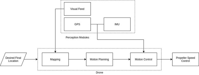
Drones use four propellers to move in a 3D world, with control and perception algorithms playing crucial roles. Control algorithms determine the propeller rotational speed, using a linear PID controller. Adaptive control handles unpredictable winds and atmospheric objects. Perception algorithms process sensors like accelerometer, gyroscope, and magnetometer to determine motion characteristics. Kalman filters filter sensor readings for stable results. Image processing algorithms may also run on the live camera feed for real-time analysis onboard the drone or via cloud computing. Autonomous drone navigation is a growing technological advancement that aims to eliminate the need for teleoperation in drones. Similar to commercial airplanes, autonomous drones in 3D space face less challenges due to the absence of dynamic objects at high altitudes. However, they still require intelligent sensing near ground level due to more obstacles and dynamic objects. Autonomous drones run localization, motion planning, mapping, and control algorithms similar to mobile robots. However, 3D navigation introduces its own variables, such as tolerance for inaccuracies due to noise, lower GPS accuracy, and air turbulence. Autonomous drones don’t need a large occupancy grid, but simple search algorithms like A* or Djikstra can navigate along streets or follow a projectile path.
Challenges and Future of Autonomous Drones
Autonomous drones face challenges in implementing and sustaining their capabilities due to battery power limitations, lack of quick ROI (return on investment), and insufficient control mechanisms. They struggle to handle dynamic situations without manual intervention or active weather perception, and remote communication with cloud infrastructure is challenging due to weaker mobile networks and high latency satellite communication. Despite their potential, these limitations limit commercial scalability and revenue generation. Enhancements in edge computing and control algorithms could improve autonomous drone control, but regulations and infrastructure development are necessary for large-scale commercial viability. Despite these challenges, autonomous drones have potential lifesavers in critical situations like emergency package delivery.
The Best Military Drones In The World In 2023
There are various types of drones used by armed forces, categorized into four categories: microdrones, small tactical drones, medium-sized reconnaissance drones, and large combat and surveillance drones. Microdrones, such as the Black Hornet, are used for spying over walls in Afghanistan. Small tactical drones, like the Fulmar X, are used for ISTAR (Intelligence, Surveillance, Target Acquisition, and Reconnaissance) capabilities. Medium-sized reconnaissance drones, also known as Medium Altitude Long Endurance (MALE) or High-Altitude Long Endurance (HALE) drones, are used for ISTAR and have a range of about 100 kilometers. The Northrop Grumman Global Hawk, the largest and most expensive combat and surveillance drone, has sophisticated ISTAR capabilities and flies at altitudes above commercial air traffic. Below are reported some of the most advanced drones in 2023.
#1 – MQ-9 Reaper:
The General Atomics MQ-9 Reaper is a US Air Force UAV used for offensive strikes, capable of both remotely controlled and autonomous flight operations. It operates with a ground control station and a US-based crew. The UAV is powered by a Honeywell TPE331-10GD turboprop engine producing a maximum of 900 shaft horsepower, giving it a cruise speed of about 230 mph (200 knots). The drone can carry 602 gallons of fuel and has a range of 1,150 miles. It can loiter at its flight ceiling of 50,000 feet for more than 27 hours conducting surveillance using sophisticated cameras, sensors, and radar. The Reaper can carry a payload of 3,750 pounds consisting of a variety of attack weapons.The Air Force Special Operations Command highlights its unique capability to perform strike, coordination, and reconnaissance against high-value, fleeting, and time-sensitive targets due to its significant loiter time, wide-range sensors, and precision weapons.
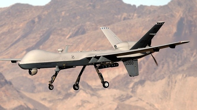
Height: 12.5 feet
Wingspan: 66 feet
Weighs (empty): 4,900 pounds
Cruise speed: 230 mph (200 knots)
Range: 1,150 miles
Max Operating Altitude: 50,000 feet
Payload: 3,750 pounds
#2 – B.A.E. Systems Taranis (Under Development)
Taranis is a large-scale unmanned combat aerial vehicle (UCAV) designed to demonstrate ISTAR capabilities, including sustained surveillance, target marking, intelligence gathering, adversary deterrence, and hostile territory strikes. It features pre-programmed waypoint tracking, takeoff, and landing procedures, and AI features for objective modification. The British Ministry of Defence (MOD) unveiled the fully developed Taranis UCAV prototype in 2010, followed by high-speed taxi tests in 2013. The first test flight was conducted in August 2013, and in-flight footage was released in July 2014. The UCAV, built with a 9.1-meter wingspan, 11.35-meter barrel length, and a height of 4 meters, weighs 8,000 kg and is powered by a Rolls Royce Adour Mk. 951 turbofan engine. It has two internal weapons bays and an option for installing electro-optical and radar sensors.
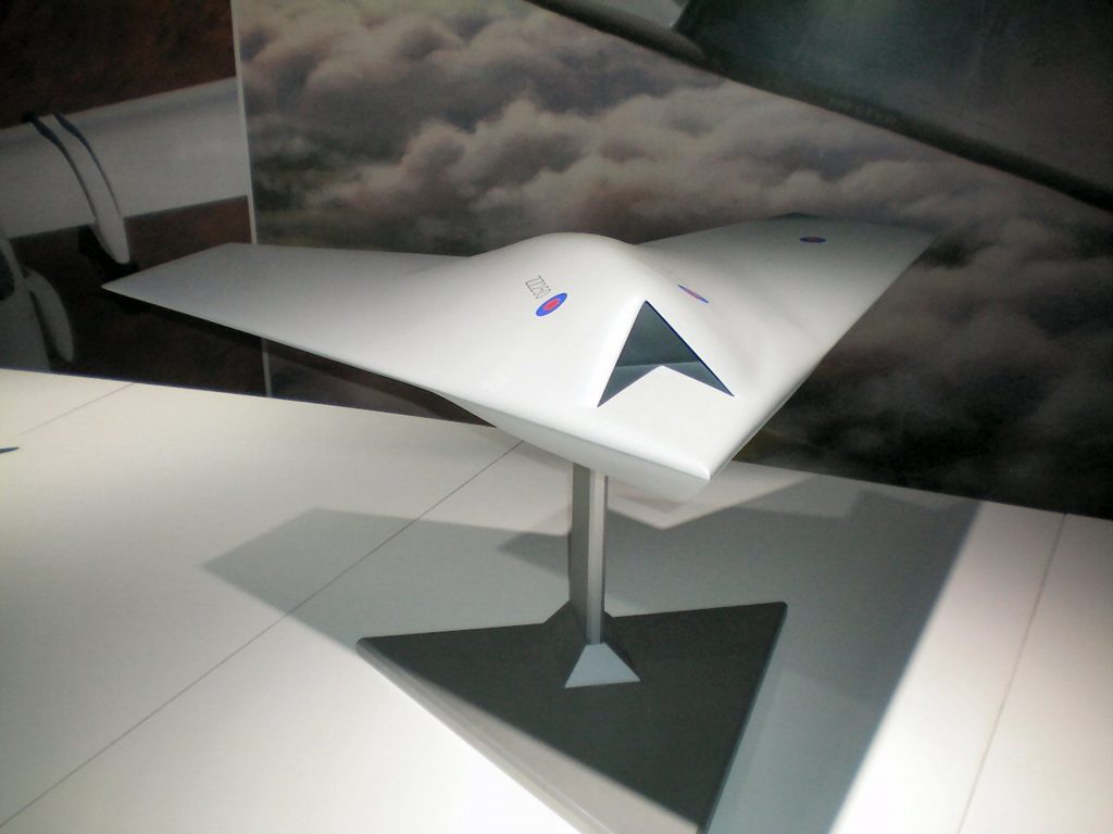
Height: 13.12 feet
Wingspan: 30 feet
Weighs (empty): 17,637 pounds
Cruise speed: Mach >1
Range: Not available
Max Operating Altitude: Not available
Payload: Not available
#3 – Bayraktar Kizilema
Baykar, a Turkish company, has developed the Bayraktar Kizilelma Fighter, an advanced unmanned aerial vehicle (UAV) with stealthy design and advanced maneuvering capabilities. The drone, powered by a Ukrainian Al-25T turbofan, can reach a cruise speed of 0.6 Mach and 500 nautical miles, and can stay airborne for five hours. It features low radar cross section, high situational awareness, and autonomous takeoff and landing. Baykar plans to develop two supersonic models using the Ukrainian Ivchenko-Progress AI-322 afterburning engines. The Kizilelma completed its inaugural flight in December 2022, and is slated for duty aboard the TCG Anadolu amphibious assault ship. Both the U.S.-built Kratos XQ-58 Valkyrie drone and Russia’s Sukhoi S-70 Okhotnik are currently in development with similar features.
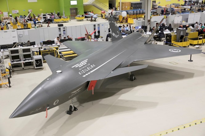
Height: 10 ft 10 in
Wingspan: 32 ft 10 in
Weighs: 8.5 tons including 1.5 tons of ordnance
Max speed: 0.9 Mach
Range: 500 nautical miles
Max Operating Altitude: 30,000 feet
Pentagon has received “several hundreds” of new reports of UFOs
The truth is out there
The Pentagon has received several hundreds of new reports of unidentified flying objects, but no evidence of alien life has been found so far. The All-domain Anomaly Resolution Office (AARO) was established in July to track unidentified objects in the sky, underwater, or in space, or potentially an object that can move between domains. Between 2004 and 2021, US intelligence agencies reported 144 such encounters, with 80 captured on multiple sensors. Since then, there has been more reporting, with an updated report expected by the end of the year.
The new office was established to examine the question of extraterrestrial life and to address the security risk posed by encounters with unknown flying objects by military installations or aircraft. Congress held its first hearing in over half a century on the topic, expressing concern that the objects could create a security risk. The office is working on improving its ability to identify unknown objects, such as recalibrating sensors focused on known adversary aircraft or drone signatures. The new office is coordinating with the Pentagon and the US intelligence community to get the signatures of US technology to rule out those aircraft or drones.
The Pentagon’s investigation covers incidents reported since 1996, but language in the new defense spending bill would extend that 75 years into the past.
The name has been changed from Unidentified Aerial Phenomena to All Domain Anomaly to account for the fact that some of the investigations deal with unexplained sightings underwater, on the surface and in space, although most of the reports still deal with aerial phenomena.
The AARO was set up in July and is responsible for not only tracking unidentified objects in the sky, but also underwater or in space — or potentially an object that has the ability to move from one domain to the next.
The office was established following more than a year of attention on unidentified flying objects that military pilots have observed but have sometimes been reluctant to report due to fear of stigma.
In June 2021 the Office of the Director of National Intelligence reported that between 2004 and 2021, there were 144 such encounters, 80 of which were captured on multiple sensors.
Since then, “we’ve had lots more reporting,” said anomaly office director Sean Kirkpatrick.
Musk’s Neuralink is now approved for human trials
Neuralink, a neurotechnology company founded by Elon Musk in 2016, has achieved a milestone by receiving FDA approval to begin human trials. However, there are still issues that need to be addressed before the technology can be used in clinical trials.
Neuralink is making a Class III medical device called a brain-computer interface (BCI) that connects the brain to an external computer via a Bluetooth signal. The device is implanted within a small disk-shaped cutout in the skull using a precision surgical robot, which splices thousands of tiny threads from the Link to certain neurons in the brain. Each thread is about a quarter the diameter of a human hair.
Potential benefits
Neuralink’s BCI could revolutionize treatment for conditions such as Parkinson’s disease, epilepsy, and spinal cord injuries. It could also be used to treat obesity, autism, depression, schizophrenia, and tinnitus. Other neurotechnology companies and researchers have already developed BCI technologies that have helped people with limited mobility regain movement and complete daily tasks.
The long road to approval for human trials
Neuralink announced in February 2021 that it was working with the FDA to secure permission to start initial human trials. In March 2022, Neuralink made a further application to the FDA to establish its readiness to begin human trials. On 25 May 2023, Neuralink finally received FDA approval for its first human clinical trial. This approval comes less than six months after the US Office of the Inspector General launched an investigation into Neuralink over potential animal welfare violations. The FDA had a list of issues that needed to be resolved before human trials could commence, most of which called for Neuralink to perform thorough and repeated testing and data collection over an extended period. It can be said with certainty that all of the issues have been fully resolved, but considering the rigor of the FDA’s approval process, we might conclude they have been resolved to a point of satisfaction for the FDA.
Risks
A precision robot known as Implant/r1 performs the surgical procedure to implant the Neuralink BCI. This robot surgeon had to be put through its paces to gather evidence that it could reliably and safely implant and remove the Neuralink BCI without damaging surrounding brain tissue or creating the risk of infection, bleeding, inflammation, or scarring. Once implanted, the Neuralink BCI must function as intended and not cause unwanted side effects such as seizures, headaches, mood changes, or cognitive impairment. Overheating lithium-ion batteries can pose a great risk to BCI users. The longevity of the battery was also taken into account, as well as how easy it would be to safely replace from its position under the skin behind the ear. Additionally, there is the risk of wire migration, as the Link consists of a disk-shaped chip with very thin wire electrodes that connect to neurons in the brain.
The companies racing to make a hypersonic aircraft
Hypersonic commercial flight is an ambitious goal, but companies are developing the technologies needed to propel passengers to Mach 5 and beyond. Hypersonic aviation companies have long, sleek aircraft designs, ideas, and ambitious R&D programs.
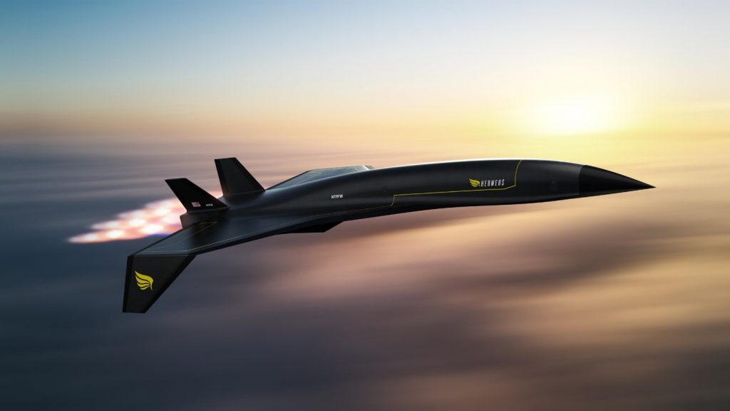
Companies such as Hermeus and Stratolaunch in the US and Australia-based Hypersonix are leading hypersonic aircraft development.
Hermeus’ Quarterhorse is expected to fly next year and will be capable of Mach 4+. It is being developed primarily to test Hermeus’ Chimera turbine-based combined cycle engine, which it intends to use in its future hypersonic aircraft.
Stratolaunch’s Mach 6+ Talon-A is expected to fly before the end of this year and will be the first fully hypersonic-capable vehicle with an integrated propulsion system, a liquid-fuelled rocket engine. It will be air-launched from the company’s Roc carrier aircraft, which is the world’s largest aircraft with a wingspan of 385ft (120m).
Crucially, Talon-A will be reusable. Current flight testing at hypersonic speeds is done with testbeds that crash land. This means only relatively small amounts of data are produced and recovered.
Stratolaunch is agnostic about who they are testing for and is trying to advance the technology for everyone.

Stratolaunch plans to fly Talon-A once every 30 days by the end of the year. The separation test is next, followed by the first expendable launch and landing vehicles. Roc provides flexibility with the size of the pylon, allowing for the best aerodynamic conditions for release. Stratolaunch is a testing services company.
Hypersonix development
Hypersonix is taking steps to develop a space-launch platform and hypersonic aircraft using Australian Government funding. Dr Michael Smart, chief technology officer, director and head of R&D at Hypersonix, lists the major technical challenges facing hypersonic flight as thermal management of the airframe and the development of a way to facilitate horizontal take-off. Hypersonix plans to fly a testbed next year, Dart AE, which will flight test the company’s hydrogen-fueled Spartan scramjet engine for the first time. Rocket Lab is supplying a rocket booster for Dart which will propel it to Mach 5, after which Spartan will ignite to produce speeds of up to Mach 12. Dart will be launched using a guided rocket, although Hypersonix has plans to develop a more complex, re-usable three stage launch system called Wirraway. Hypersonix is already working with Kratos and Smart sees the potential in partnerships with other companies and countries.

(Images: Hypersonix)
Partnership Plan
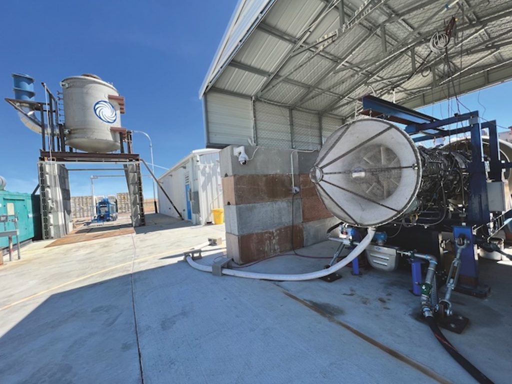
Reaction Engines is a hypersonic R&D company founded in 1989 to develop a spaceplane. President Adam Dissel heads up the business in the USA and is pragmatic about the challenge of developing a hypersonic aircraft. Reaction works with BAE Systems, Rolls-Royce, the UK’s MOD and the US Air Force (USAF). The partnerships have requirements that must be fulfilled and pragmatic near-term targets. In January, Reaction successfully completed a ground testing campaign in Colorado with the USAF to demonstrate the suitability of its precooler technology to boost the performance of current generation fighter jet engines. The precooler test item allows current jets to fly at a much higher speed without a brand new engine.

Dissel believes that hypersonic aircraft propulsion systems based on rocket engine technology will be complex, difficult to maintain, and have low lifetimes. Reaction is working in the UK on the HVX program, which aims to develop hypersonic technologies including air-breathing propulsion engines, thermal management systems, and advanced vehicle concepts. As part of the program, Reaction’s precooler technology is being combined with a subscale jet engine for ground testing and then scaled up to engine sizes large enough for use in aircraft. Dissel is excited about the high-speed market, believing that there are commercial and defense angles and that it is a partnership approach with other companies and different governments and countries to make it real.
Destinus Project (Europe)
Destinus, a European company founded in 2021, has grown to 80 people and has offices in Switzerland, Toulouse and Paris. It plans to build two hypersonic aircraft, one transoceanic and one transglobal, both hydrogen-fueled and flying at altitudes of 30-40km. It is conducting flight testing using subsonic prototypes and ramping up quickly towards flying a supersonic prototype next year. The thermal management system is a patented concept that uses pipes carrying hydrogen to reduce temperature at the hot surfaces of the aircraft. The company is also developing hydrogen afterburners and an autopilot system and is doing research on the vehicle design.


Destinus’ technology to-do list for a hypersonic aircraft includes thermal management and a propulsion system that can enable horizontal take-offs and landings. The decision to use hydrogen fuel was made early on due to environmental and design considerations. Hydrogen is lightweight and more efficient than Jet A fuel at speeds above Mach 3 and ranges of more than 3,000km.
Destinus is an ambitious testing program that will burn through money as fast as it combusts hydrogen. The company is seeking funding support from governments in the form of joint R&D programs. Destinus plans to sell access to its test facilities to other companies as and when they become available. The company is also looking at the possibility of developing hypersonic-capable unmanned vehicles that could be used for R&D and defense applications as a revenue source. Lofqvist (senior business development director) believes there is strong support for Destinus in Europe and believes market demand will exist for hypersonic passenger flights in the future.
Non-technical challenges are not driving design or development at the present moment, but most hypersonic companies are addressing innovating within thermal management and propulsion first. There is a growing awareness that surmounting the barriers to hypersonic flight will require the pooling of resources and knowledge between companies and countries.
Hypersonic propulsion is challenging
The most important details in this text are the development of a reusable, reliable engine capable of propelling aircraft to hypersonic speeds. The most successful hypersonic manned aircraft is the USA’s X-15 (it was air-launched and used rocket engines in the 1950s and 1960s), which achieved a speed of Mach 3.7. The fastest air-breathing manned aircraft is the SR71 Blackbird spy plane, which was powered by two Pratt & Whitney J58 axial flow turbojet engines and was capable of Mach 3.2. The SR71’s J58 engine is often called a turbo ramjet. Ramjets use the forward motion of the engine during flight to compress incoming air instead of a rotary compressor. They can only be used at speeds above Mach 2. The scramjet (supersonic combustion ramjet) is designed for speeds above Mach 6, but no flight tests have surpassed Mach 9.6. Companies are pursuing several propulsion technologies, but crucial to hypersonic flights is the development of a capability to power an aircraft through the lower atmosphere using conventional jet engine technology before switching to a ramjet system for hypersonic speeds.
Venus Aerospace is developing hypersonic drones and passenger aircraft.
Velontra is building an unmanned spaceplane that uses a jet engine and airbreathing propulsion.
Radian Aerospace is launching a delta-winged spaceplane Radian One that will be launched from a rocket-powered sled and used to orbit for manned missions of up to five days before returning to Earth.
AI co-pilots are ready to be used on general aviation aircraft
Avionics systems using artificial intelligence are being developed for eVTOL aircraft, but general aviation piston aircraft will be the first users. Avidyne and Daedalean formed a partnership to develop the PilotEye system in 2020. Avidyne is aiming to gain FAA certification for the system this year with concurrent validation by EASA. Schwinn (President and founder of avionics company Avidyne) expects to have finalized systems by the middle of the year. Development, validation and certification activities are ongoing in the STC program (Supplemental Type Certificate program underway at FAA and EASA).
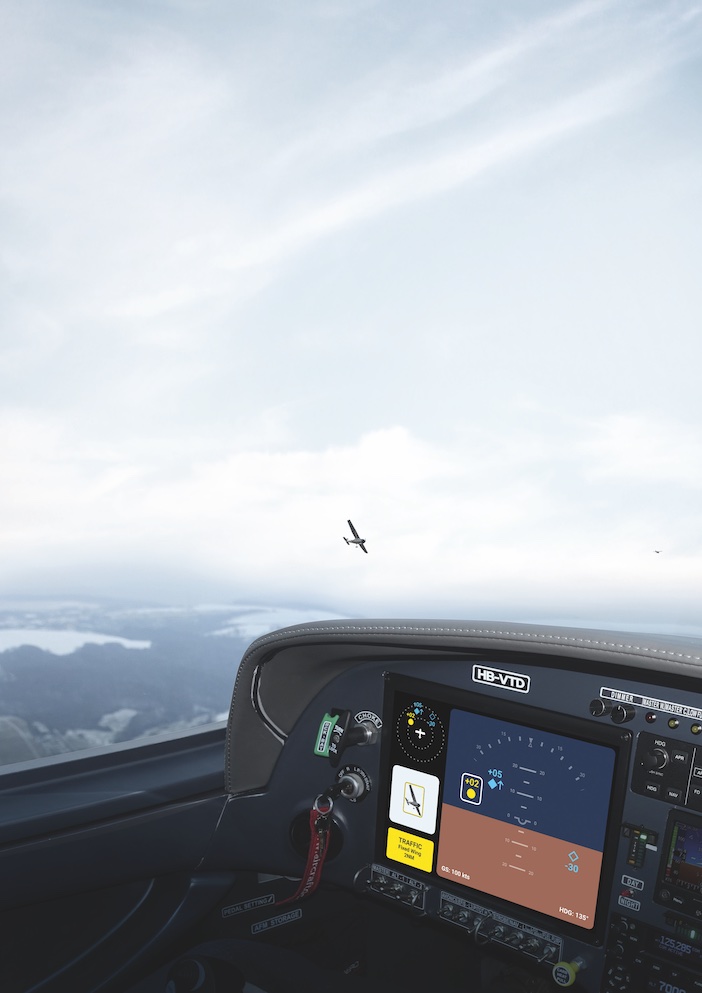
Visual acquisition
Avidyne was founded 27 years ago to bring big glass cockpit displays to general aviation cockpits. PilotEye functions will integrate with any standards-based traffic display, allowing the pilot to use an iPad to zoom in on traffic. There will be enhanced features when installed with Avidyne displays.
PilotEye is a system that can detect aircraft, drones, and obstacles. PilotEye can detect a Cessna 172 at 2 miles (3.2km) and a Group 1 drone (20 lbs, 9kg). Avidyne installs traditional avionics hardware and Daedalean provides neural network software for flight test programs.
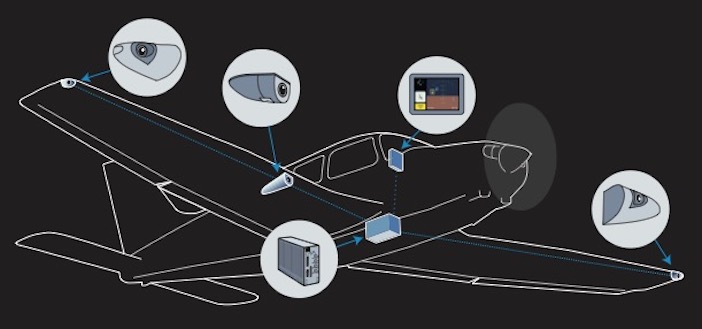
PilotEye is a real-time, critical application that uses neural networks to analyze engine data. Avidyne has flown hundreds of hours of flight tests with PilotEye and done thousands of hours of simulation. The forward-facing camera has a 60˚ field of view and the two side-facing cameras have 80˚ fields of view, producing a 220˚ panorama. The system will have three cameras initially and an optional fourth camera later, which helicopter operators may point down to find helipads or potential emergency landing locations.
Neural networks
Daedalean has been developing neural network technology for aviation since 2016, mainly as flight control systems for autonomous eVTOL aircraft. It provides an evaluation kit of its computer vision based situational awareness system, along with drawings and documentation, so airframe, avionics companies and large fleet operators can install it on their own flight test aircraft. The two-camera evaluation kit provides visual positioning and navigation, traffic detection and visual landing guidance portrayed on a tablet computer in real time. Installation is not easy and involves more than duct tape to ensure it is safe for flight. End users can buy or rent the evaluation kit or partner with Daedalean long-term in developing advanced situational awareness systems.
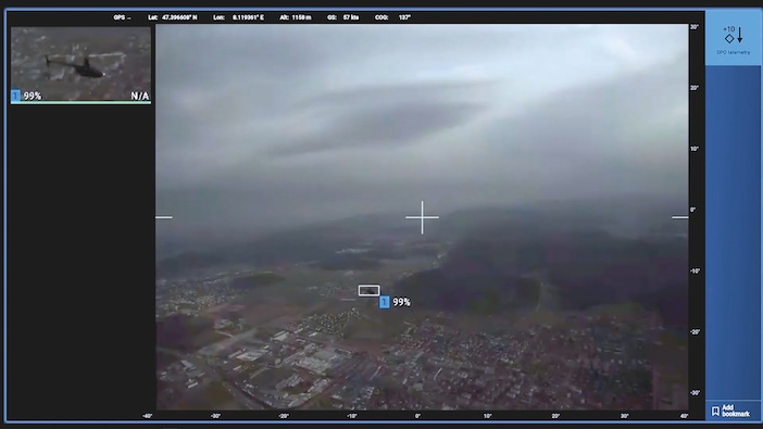
Daedalean is developing a Level 1 AI/Machine learning system to assess the performance of computer vision technology in real world scenarios. The equipment is a Level 1 AI/Machine learning system, which provides human assistance, Level 2 is for human/machine collaboration and Level 3 is a machine able to perform decisions and actions fully independently. Daedalean has collected 500 hours of flight test video recordings in rented GA aircraft and helicopters for its situational awareness system, and has gathered 1.2 million still images taken during 7,000 encounters between the data gathering aircraft and another aircraft providing the target. The code is then frozen and released to partners using Daedalean evaluation kits, and feedback from these users guides the next release. The aim is to eventually have the system interfaced with flight controls to avoid hazards such as obstacles and terrain, and to communicate with air traffic control and other Daedalean equipped aircraft.
Certification Procedure
Daedalean is working with regulators to develop an engineering process to be applied to AI and machine learning avionics during certification. The standard software development process follows a V-shaped method which confirms software conforms to requirements, standards and procedures. EASA and Daedalean have created a W-shaped process to guide certification efforts, with the middle of the W used to verify the learning process and ensure that the learning technique is correctly applied. The FAA has also evaluated whether visual-based AI landing assistance would backup other navigation systems during a GPS outage. Avionics supplier Honeywell has also partnered with Daedalean to develop and test avionics for autonomous takeoff and landing, as well as GPS-independent navigation and collision avoidance.
Honeywell Ventures is an investor in Daedalean. The Swiss company Honeywell has established a US office near Honeywell’s headquarters in Phoenix, USA. The FAA is also involved in working to bring AI and neural network machine learning to general aviation cockpits by funding R&D with US research agency MITRE. Software engineer Matt Pollack has been working on the digital copilot project that began in 2015. Flight testing of the first algorithms began in 2017 with a Cessna 172 and since then a total of 50 flight test hours have been conducted in light aircraft as well as in helicopters. The cognitive assistance provided by the digital co-pilot operates like Apple’s Siri or Amazon’s Alexa voice assistance do on the ground.
It aids a pilot’s cognition without replacing it and is enabled by automatic speech recognition and location awareness. The algorithms provide useful information with audio and visual notifications based on the context of what the pilot is trying to accomplish. The system can also provide a memory prompt.
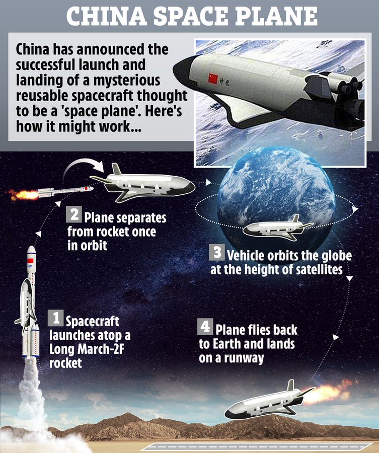
China’s mysterious space plane returns to Earth after 9-month
The robotic vehicle stayed aloft for 276 days on its second orbital flight.
The second orbital mission of China’s robotic space plane has come to a close. The mysterious reusable vehicle touched (May 8, 2023)down at the Jiuquan Satellite Launch Center in northwest China, wrapping up a 276-day mission to Earth orbit. The success of the experiment marks an important breakthrough in China’s research on reusable spacecraft technologies, which will provide more convenient and affordable round-trip methods for peaceful use of space.
The space plane launched from Jiuquan on Aug. 4, 2022, kicking off a mission short on details but long on intrigue. On Oct. 31, the vehicle ejected something into orbit, possibly a service module or a small satellite designed to monitor the Chinese space plane. Western experts think the vehicle is roughly similar to the U.S. Space Force’s robotic X-37B, which is about 29 feet (8.8 meters) long. The U.S. military is similarly tight-lipped about the X-37B, which has flown six orbital missions to date, the longest of which lasted 909 days.
Other reusable spacecraft or spaceplane projects are under consideration in China. The China Aerospace Science and Industry Corp. (CASIC) is working on its own spaceplane, named Tengyun, while commercial firm Space Transportation last year raised more than $46.3 million for its hypersonic spaceplane plans.
A number of Chinese rocket companies have also created presentations including small spaceplanes launching atop concepts for liquid rockets.
NASA tests rotary detonation engine: it will revolutionize space travel
Rotating detonation rocket engine for deep space exploration
Propulsion technology represents a key element for the realization of advanced space missions, both as regards the exploration of the Moon and Mars, and as regards the transport of cargo and people to destinations even further away in deep space. To reach this goal, engineers studying new forms of propulsion at NASA developed and tested the first rotary detonation engine, or also known as the RDRE.
The operation of a rotary detonation engine is based on supersonic combustion, known as detonation, which allows it to generate more thrust using less fuel than currently used propulsion systems. The detonations and supersonic waves that are generated inside a combustion chamber are very complex to manage, and therefore the project acquires even more importance given the state of progress.
This technology has been talked about since the 1950s, but to be honest, when it was theorized it seemed more utopian than real, at least until today. This type of engine could be used to power both human landers and interplanetary vehicles for the most distant destinations in space, such as the Moon and Mars, and could represent an alternative to other technologies currently under study, such as the nuclear thermal one of which we have talked about recently.
NASA Marshall Space Flight Center engineers and lead contributor IN Space LLC conducted a test firing on the RDRE in 2022, confirming the data obtained. The RDRE achieved its main goal by demonstrating that its equipment, made with 3D printing techniques, could operate for extended periods while withstanding the extreme conditions generated by detonations. During testing, the RDRE produced approximately 2 tons of thrust for approximately one minute with an average chamber pressure of 47 kg per square inch, the highest pressure level recorded for this type of engine.
The RDRE uses GRCop-42, a copper alloy developed by NASA, and the powder bed fusion process to allow the engine to operate in extreme conditions for longer periods.
The results obtained during the tests represent an important step towards the use of this technology on future spacecraft, which will allow NASA and the commercial space industry in general, to carry ever-increasing payloads to destinations in deep space, a fundamental element to make space exploration more sustainable.
Following the positive results obtained with the RDRE, NASA engineers are working to develop an even more powerful fully reusable RDRE engine, to further identify the performance advantages over traditional liquid engines. We leave you with the video of the incredible rotary detonation engine test.
How Rotating detonation engine works ?
A rotating detonation engine (RDE) is an engine using a form of pressure gain combustion, where one or more detonations continuously travel around an annular channel. Computational simulations and experimental results have shown that the RDE has potential in transport and other applications.
In detonative combustion, the results expand at supersonic speed. It is theoretically more efficient than conventional deflagrative combustion by as much as 25%. Such an efficiency gain would provide major fuel savings.
Disadvantages include instability and noise.
The basic concept of an RDE is a detonation wave that travels around a circular channel (annulus). Fuel and oxidizer are injected into the channel, normally through small holes or slits. A detonation is initiated in the fuel/oxidizer mixture by some form of igniter. After the engine is started, the detonations are self-sustaining. One detonation ignites the fuel/oxidizer mixture, which releases the energy necessary to sustain the detonation. The combustion products expand out of the channel and are pushed out of the channel by the incoming fuel and oxidizer. Although the RDE’s design is similar to the pulse detonation engine (PDE), the RDE is superior because the waves cycle around the chamber, while the PDE requires the chambers to be purged after each pulse.
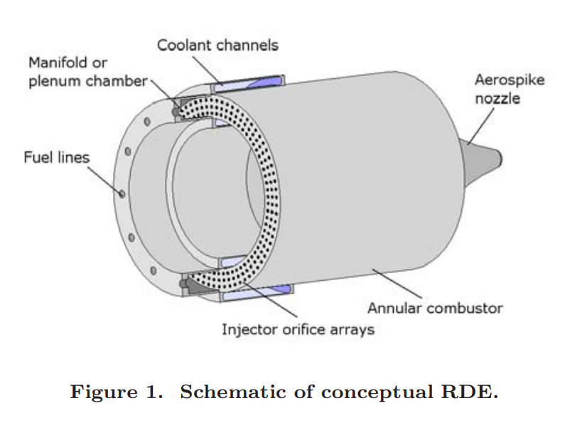
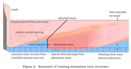
A possible RDE configuration is shown schematically in Fig. 1 while an unwrapped schematic of the rotating detonation wave is shown in Fig. 2. Reactants are fed either separately or premixed into an annular combustor from the bottom. A detonation wave and possibly multiple waves rotate in the annulus just at the exit of the injector arrays, consuming the reactants feeding continuously from the bottom. The high pressure is then reduced to the inlet pressure after passage of the detonation wave which allows the reactants to again feed into the annulus, thereby allowing chemical reactions to continue to sustain the detonation wave. The reactants penetrate a certain distance into the annulus which roughly marks the end of the detonation wave. Further away, the detonation wave degenerates into a blast wave. This structure has previously been called a combined detonation-shock wave35,36 or detonation wavelet. The figure shows a postulated contact surface burning due to the hot environment exceeding the autoignition temperature. Figure 2 shows penetration of the hot, high pressure products just downstream of the detonation wave into the injector. A complex wave interaction is set up, dependent on the properties of the reactants and products, as well as on the geometry of the injector. Preliminary indications are that such a scheme can be operated safely.
Just 45 Days to Get to Mars by nuclear propulsion, NASA and DARPA will test it soon
Nuclear Propulsion Could Help Get Humans to Mars Faster
NASA and DARPA are to demonstrate a nuclear thermal rocket engine in space, with a view to using the technology to send crewed missions to Mars. The Demonstration Rocket for Agile Cislunar Operations (DRACO) program will develop and flight test in space nuclear thermal propulsion technology that could be used to transport astronauts to Mars and beyond. The research agencies plan to send the DRACO test vehicle into space and run the nuclear engine in 2027.
NASA’s Space Technology Mission Directorate (STMD) will lead technical development of the nuclear thermal engine, which will be integrated with an experimental spacecraft developed by the Defense Advanced Research Projects Agency (DARPA). A nuclear thermal rocket engine uses a fission reactor to generate extremely high temperatures. The engine transfers the heat produced by the reactor to a liquid propellant, which is expanded and exhausted through a nozzle to propel the spacecraft.
Engineers believe that nuclear thermal rockets can be three or more times more efficient than conventional chemical propulsion. Using a nuclear thermal rocket will enable faster transit times, reducing risk for astronauts. Reducing transit time is a key component for human missions to Mars, as longer trips require more supplies and more robust systems. Other benefits to space travel include increased science payload capacity and higher power for instrumentation and communication, said NASA.
DARPA is acting as the contracting authority for the development of the entire stage and the engine, which includes the reactor. DARPA will also lead the overall program including rocket systems integration and procurement, approvals, scheduling, and security, cover safety and liability, and ensure overall assembly and integration of the engine with the spacecraft. Over the course of the development, NASA and DARPA will collaborate on assembly of the engine.
Nuclear thermal rocket engine testing was last conducted by the USA more than 50 years ago under NASA’s Nuclear Engine for Rocket Vehicle Application and Rover projects. NASA and the Soviet space program spent decades researching nuclear propulsion during the Space Race. A few years ago, NASA reignited its nuclear program for the purpose of developing bimodal nuclear propulsion – a two-part system consisting of an NTP and NEP element – that could enable transits to Mars in 100 days.
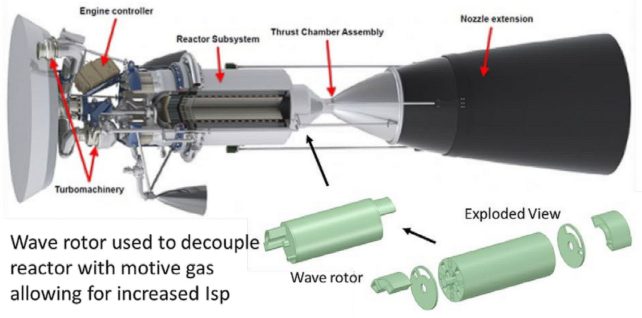
As part of the NASA Innovative Advanced Concepts (NIAC) program for 2023, NASA selected a nuclear concept for Phase I development. This new class of bimodal nuclear propulsion system uses a “wave rotor topping cycle” and could reduce transit times to Mars to just 45 days. The proposal, titled “Bimodal NTP/NEP with a Wave Rotor Topping Cycle,” was put forward by Prof. Ryan Gosse, the Hypersonics Program Area Lead at the University of Florida and a member of the Florida Applied Research in Engineering (FLARE) team.
Gosse’s proposal is one of 14 selected by the NAIC this year for Phase I development, which includes a US$12,500 grant to assist in maturing the technology and methods involved. Other proposals included innovative sensors, instruments, manufacturing techniques, power systems, and more.
For Nuclear-Thermal Propulsion (NTP), the cycle consists of a nuclear reactor heating liquid hydrogen (LH2) propellant, turning it into ionized hydrogen gas (plasma) that is then channeled through nozzles to generate thrust. Several attempts have been made to build a test this propulsion system, including Project Rover, a collaborative effort between the US Air Force and the Atomic Energy Commission (AEC) that launched in 1955.
In 1959, NASA took over from the USAF, and the program entered a new phase dedicated to spaceflight applications. This eventually led to the Nuclear Engine for Rocket Vehicle Application (NERVA), a solid-core nuclear reactor that was successfully tested. With the closing of the Apollo Era in 1973, the program’s funding was drastically reduced, leading to its cancellation before any flight tests could be conducted. Meanwhile, the Soviets developed their own NTP concept (RD-0410) between 1965 and 1980 and conducted a single ground test before the program’s cancellation.
Nuclear-Electric Propulsion (NEP), on the other hand, relies on a nuclear reactor to provide electricity to a Hall-Effect thruster (ion engine), which generates an electromagnetic field that ionizes and accelerates an inert gas (like xenon) to create thrust. Attempts to develop this technology include NASA’s Nuclear Systems Initiative (NSI) Project Prometheus (2003 to 2005). Both systems have considerable advantages over conventional chemical propulsion, including a higher specific impulse (Isp) rating, fuel efficiency, and virtually unlimited energy density. While NEP concepts are distinguished for providing more than 10,000 seconds of Isp, meaning they can maintain thrust for close to three hours, the thrust level is quite low compared to conventional rockets and NTP. The need for an electric power source, says Gosse, also raises the issue of heat rejection in space – where thermal energy conversion is 30-40 percent under ideal circumstances.
And while NTP NERVA designs are the preferred method for crewed missions to Mars and beyond, this method also has issues providing adequate initial and final mass fractions for high delta-v missions. This is why proposals that include both propulsion methods (bimodal) are favored, as they would combine the advantages of both. Gosse’s proposal calls for a bimodal design based on a solid core NERVA reactor that would provide a specific impulse (Isp) of 900 seconds, twice the current performance of chemical rockets.
Gosse proposed cycle also includes a pressure wave supercharger – or Wave Rotor (WR) – a technology used in internal combustion engines that harnesses the pressure waves produced by reactions to compress intake air. When paired with an NTP engine, the WR would use pressure created by the reactor’s heating of the LH2 fuel to compress the reaction mass further. As Gosse promises, this will deliver thrust levels comparable to that of a NERVA-class NTP concept but with an Isp of 1400-2000 seconds. When paired with a NEP cycle, said Gosse, thrust levels are enhanced even further: “Coupled with an NEP cycle, the duty cycle Isp can further be increased (1,800-4,000 seconds) with minimal addition of dry mass. This bimodal design enables the fast transit for manned missions (45 days to Mars) and revolutionizes the deep space exploration of our Solar System.”
Based on conventional propulsion technology, a crewed mission to Mars could last up to three years. These missions would launch every 26 months when Earth and Mars are at their closest (aka. a Mars opposition) and would spend a minimum of six to nine months in transit. A transit of 45 days (six and a half weeks) would reduce the overall mission time to months instead of years. This would significantly reduce the major risks associated with missions to Mars, including radiation exposure, the time spent in microgravity, and related health concerns. In addition to propulsion, there are proposals for new reactor designs that would provide a steady power supply for long-duration surface missions where solar and wind power are not always available. Examples include NASA’s Kilopower Reactor Using Sterling Technology (KRUSTY) and the hybrid fission/fusion reactor selected for Phase I development by NASA’s NAIC 2023 selection.
NASA, the Department of Energy (DOE) and industry are also developing advanced space nuclear technologies for multiple initiatives to harness power for space exploration. Through NASA’s Fission Surface Power project, DOE awarded three commercial design efforts to develop nuclear power plant concepts that could be used on the surface of the Moon and, later, Mars.
Orbital Debris Removal Technologies
Access to space is becoming easier and currently one can launch small spacecraft into Low Earth Orbit (LEO) for a few hundreds of thousands of dollars. According to the U.S. Space Surveillance, there are half a million space objects in Low Earth Orbit (LEO), and only 30,000 are actively tracked. 23,000 pieces of orbital debris are larger than 10 cm and provide more velocity when in orbit. The estimated population of particles between 1-10 cm in diameter is approximately 500,000. There are 100,00,000 pieces of debris that are smaller than 1mm. The United States is responsible for 30% of all orbital space debris. The debris is frequently in transit the orbits of hundreds of operational spacecrafts. Additionally, most of the debris were inserted into long-duration orbits, with orbital lifetimes imagined at multiple decades and centuries. Collisions can lead to huge investment efforts, including expensive fixes. There have been three major collisions since 2005. They all involve a large intact body, typically a satellite, colliding with smaller pieces. With these smaller pieces still in orbit, more collisions will occur, thus creating more space debris. The term “debris removal” implies taking active measures to remove something from orbit and not letting its orbit decay on its own. There are three main removal technology concepts: Laser Solutions, Electrodynamic Tethers, and Deployable Nets.
Active orbit debris removal
De-orbiting of the debris is mainly focused on using different mechanism for changing orbital velocity. This is done by applying a force (or impulse). In the limiting case where the orbital velocity is reduced to zero, the object will only have gravitational potential energy and, thus, “fall” back to Earth. The three technologies considered are different in the way they impart this force or impulse. The lased-based approaches impart this force or impulse in a contactless fashion. Electrodynamic tethers are objects that are deployed from or attached to an object that will result in forces being applied to it form Earth magnetic field. Nets apply this force by physical contact with the object.
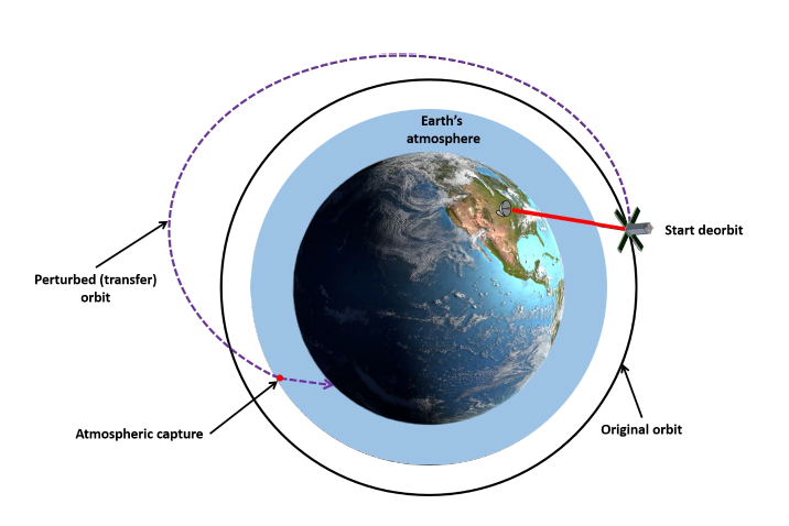
As depicted in figure below, all three of the orbital debris removal systems discussed here effectively perturb the original orbit of the object so that it eventually gets captured by the atmosphere.
Laser Orbital Debris Removal (LODR)
Laser orbital debris removal (LODR) is a contactless method in that applying a force or impulse to the object to be de-orbited does not require to physically contact it. The system uses a laser either on Earth or in orbit to shone on the object that is to be deorbited. One of the earliest proposed use of LODR was by NASA in 1996 with Project Orion. Project Orion [1] was created as a “laser broom” to remove all pieces of debris less than 10 cm under 1100 km in two years. This LODR as used a pulsed laser.
The LODR solution is considered successful, especially for larger debris. With having the ability to capture debris from the ground and in space, researchers can explore a solution with multiple options. There are concerns with this laser orbital removal technology capturing the smaller pieces (less than 1mm).
As depicted in the figure below, the laser, which is either a ground- or space-based one applies a force or impulse to the debris. This in turn changes the orbital speed and eventually orbital radius “r”.
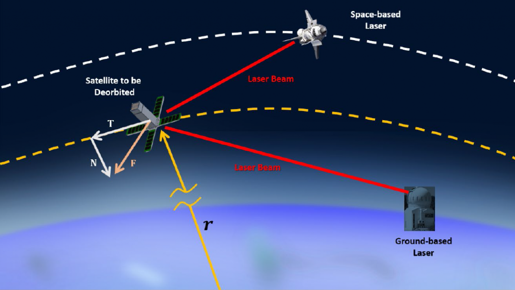
The total force imparted to the debris is F and can be resolved into its tangential component T and radial/normal component N. As will be discussed below, the magnitude of T and N depend on many factors including the orientation (attitude) of the debris. The force applied by the laser beam causes a change in the debris orbital velocity which puts it into a transfer orbit with a perigee deep in the dense part of the atmosphere ash shown in Figure 1.
The laser deposits energy into the material of the debris which causes ablation of the material. The ablation products leave the debris at a high speed and carry with them some of the momentum of the debris. In effect, the ablation products are acting as a miniature thruster that is applying an impulse to the debris. The net thrust that is imparted by the ablation products depends on the orientation of the debris. As show shown in Figure above, if the flat part on which the laser shines is not perpendicular to the original velocity vector, the resulting force will have both a tangential component T and a normal component N.
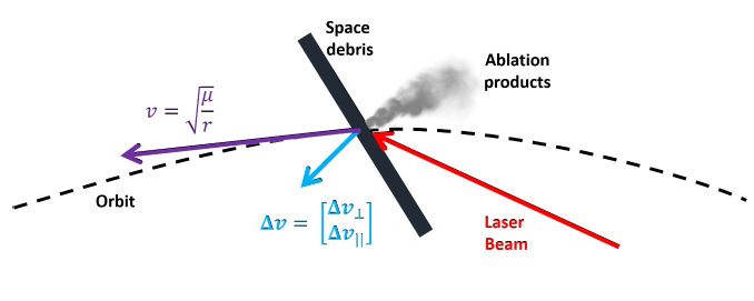
Referring to Figure 3 above, the magnitude of the tangential velocity change |Δv| applied to the debris is described by the following equation:
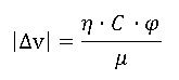
The efficiency factor ƞ accounts for the combined effects of improper thrust direction on the target, target shape and tumbling. The term φ is the laser fluence which is a measure how much energy is contained in the laser. The mechanical coupling term C measures how much of how effectively the laser energy is converted into momentum change of the debris. The last term in this equation μ is the debris areal mass density and is a description of the debris’ geometry.
The equation above shows, the change in orbital velocity achieved by LODR depends on many factors including the laser being used as well as the geometry and construction of the debris’ host spacecraft.
Below are reported the characteristics of LODR on common materials used on spacecraft ([2], [3]).
| Debris Material | Laser Fluence Required (J/m2) | Mechanical Coupling Coefficient |
| Aluminum (Al) | 11.7 | 3.94E+29 |
| Gold (Au) | 16.9 | 2.20E+36 |
| Carbon (C) | 15.68 | 3.20E+27 |
| Iron (Fe) | 13 | 1.19E+32 |
| Lithium (Li) | 10.4 | 1.05E+23 |
| Molybdenum (Mo) | 5.2 | 5.46E+36 |
| Tungsten (W) | 20.8 | 2.48E+38 |
Below are reported the Advantages and Disadvantages of LODR
Advantages:
- Contactless, no interaction with space debris
- lasers can work with most materials commonly used (see tab above)
Disadvantages:
- Difficulties to be aware on the orientation of the debris (required for tangential velocity change)
Electrodynamic Tethers (EDT)
Electrodynamic Tethers (EDT) are systems that take advantage of Earth’s magnetic field to generate an electromotive force which can be used apply a positive or negative Δv to an object in orbit. Tethers are long strands of fibers that are used to connect or couple objects together to operate as one system. In space, tethers are typically launched or directed into Earth’s orbit and will align with the movement of Earth’s magnetic field ([4], [5], [6], [7]). Some tethers will convert potential energy to kinetic energy while others act as motors. Thus, they can be used as a deorbiting system or a “boost” system for changing the orbit of Earth orbiting objects. In other words, some tethers will convert potential energy to kinetic energy while others act as motors. This solution has been predicted better for mega-constellations due to the amount of electrodynamic drag they possess. There have been several EDT demonstrations missions most the TSS-1 and TSS-1R mission, Plasma Motor Generator (PMG) experiments and NASA’s Propulsive Small Expendable Deployer System or ProSEDS mission.
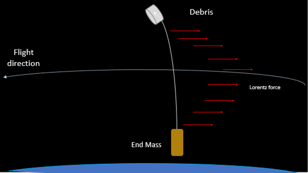
Figure 4 above shows the principle of an electrodynamic tether solution for removing orbital debris. The tether was deployed and is shown orbiting around the Earth with an end mass. Current runs through the tether, working along with the geomagnetic field of the planet. The bare side of the tether attaches itself to the orbital debris using a hooker or connecter. After capture, the end mass allows the system to rotate and release the tether and orbital debris. The system then deorbit itself and burns up into the atmosphere, removing the debris overall. This concept is used in the KITE experiment from JAXA. Previous studies show that debris objects that should be removed from crowded orbits can re-enter the Earth’s atmosphere within one year. Having a system with at least a 10-km tether on a host satellite should be able to eliminate that [8].
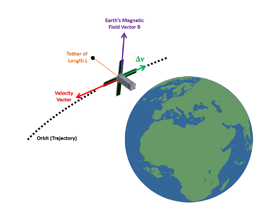
If a space craft can deploy a long cable of length L cable of carrying an electric current I, then as it orbits the interaction between Earth’s magnetic field B and the cable will generate a force given by:
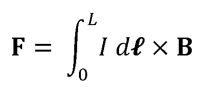
Figure below shows a simplistic diagram of the relationship between the orientation of the cable and the force F that would be generated by a deployed cable in orbit. The result force will be orthogonal to both the cable and Earth’s magnetic field. As such, it acts in the direction opposite to the velocity vector of the object that deployed the cable. Thus, it is effectively delivering negative Δv to the space craft and causing its orbit to decay.
Below are reported the Advantages and Disadvantages of Electrodynamic Tether:
Advantages:
- Being EDT simple and passive device, it can be easily installed on many small satellites
- It can be used not only to de-orbit a small spacecraft but also for increasing their orbital altitude as well.
- it can be used to generate electrical power which can be used to charge batteries thereby supplementing the function of solar panels. Unlike solar panels, however, they can generate power regardless if the sun is in view or not
Disadvantages:
- Risk of impact with orbital debris
- It only works on objects that have it designed and built into them. This means that it cannot be used on random space debris unless there is a way to attach a compact and self-contained EDT system to the debris on orbit.
- Mechanism used for reeling out the cable can be difficult to design, they can be made to be rather compact and fit in most small space vehicles
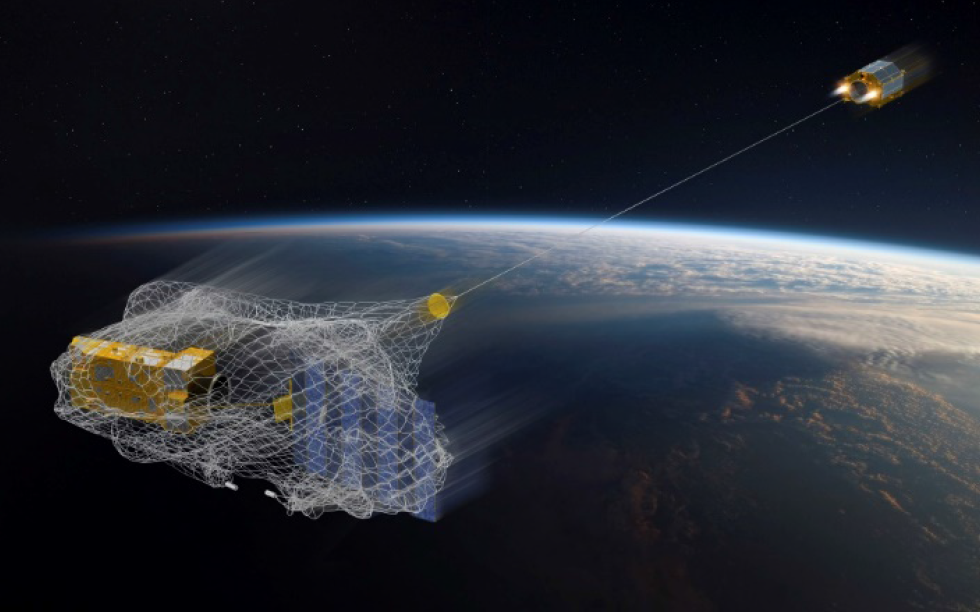
Deployable Nets
Deployable nets are perhaps the easiest to understand technology that has been proposed for orbital debris removal. The idea is to deploy something akin to a fisher’s net called a tether-net from a chaser spacecraft (still connected to the net) in the proximity of orbital debris. The tether-net is deployed ahead of the debris to be removed. The debris slowly drifts into and gets tangled by the tether net. Then the chaser spacecraft fires thrusters to change the orbit of itself and of the debris in the net such that they will reenter Earth’s atmosphere and burn.
While conceptually simple, the design of the nets themselves and the debris removal operation using them can be complex. For example, proposed nets are a collection of elastic rods connected. The rods can be connected by knots, or elastic joints. As a deformable body, the elastic rod can bend and form around the target to secure and capture it. Most nets considered for orbital debris removal are Cosserat nets. Cosserat nets consist of a network of elastic rods and elastic joints that link together to create a deformable body [9].
Furthermore, nets need to have a closing mechanism to allow satellites to release net once debris is captured. These can also be complex to design and operate in space.
The deployable net solution can be explained using the practices of fishing. Fishermen locate the fish and eject a net from a safe distance. The net comes with a closing mechanism to secure capture and reel the net back up to the surface.
Figure 5 below shows the similar concept occurring with the deployable net solution in space. The net is transported into space on a host satellite in a container. Once the satellite is at desired altitude, the net is deployed and captures targeted debris using its closing mechanism. The closing mechanism would be the end points on the corners of the net to ensure proper capture. The satellite will then travel to a lower altitude and cut the net with the attached debris for it to de-orbit and burn up in the atmosphere.
Below are reported the Advantages and Disadvantages of Deployable Nets:
Advantages:
- Unlike the other solutions, deployable nets can capture a large group of debris at one time.
- Due to previous advantage, it is oneof the more cost-efficient solutions.
Disadvantages:
- The Net needs proper spatial awareness for proper capture. Without proper attitude and control practices from the host satellite, this would be difficult for the net to capture the debris.
- Risk of possible stuck onto the host satellite. This can cause issues in its operation, thus failing the mission
References:
[1] J. Campell, “Project Orion: Orbital Debris Removal Using Ground Based Sensors and Lasers,” National Aeronautics and Space Administration, MSFC, Alabama, 1996.
[2] L. Zhou, X.-Y. Li, W.-J. Zhu, J.-X. Wang and C.-J. Tang, “The effects of pulse duration on ablation ressure driven by laser radiation,” Journal of Applied Physics, vol. 117, no. 12, 31 March 2015.
[3] K.-C. Lee, T. Taira, G. Mo Koo, J. Young Lee and J. J. Yoh, “Ignition characteristics of laser-ablated aluminum at shock pressures up to 2 GPa,” Journal of Applied Physics, vol. 115, no. 1, 3 January 2014.
[4] M. Sandoval, “Space Tethers,” University of Colorado, Boulder, 2007.
[5] M. Dobrowolny and N. Stone, “A technical overview of TSS-1: The first Tethered-Satellite system mission,” Il Nuovo Cimento, vol. C, no. 17, pp. 1-12, 1994.
[6] “Plasma turbulence enhanced current collection: Results from the plasma motor generator electrodynamic tether flight,” Journal of Geophysical Research: Space Physics, vol. 100, no. A2, 1 February 1995.
[7] J. Ballance and L. Johnson, “Propulsive Small Expendable Deployer System (ProSEDS),” AIP Conference Proceedings, vol. 552, no. 1, 4 April 2001.
[8] The Aerospace Corporation, “Danger: Orbital Debris,” 4 May 2018.
[9] J. Spillmann and M. Teschner, “Cosserat Nets,” IEEE Transactions on Visualization and Computer Graphics, vol. 15, no. 2, pp. 325-338, March 2009.
THE AVIATION ALPHABET
The language of aviation came about from a need for safety. To avoid pilots and controllers mishearing each other and potentially creating an accident, a language of aviation terms and phrases were compiled in the Pilot/Controller Glossary.
To help avoid confusion with similar sounding consonants and numbers, in March 1956 the International Civil Aviation Organization (ICAO) adopted a standard phonetic alphabet for aviation use:
| LETTER | WORD | PHONIC (PRONUNCIATION) |
| A | Alfa | Al fah |
| B | Bravo | Brah voh |
| C | Charlie | Char lee |
| D | Delta | Dell tah |
| E | Echo | Eck oh |
| F | Foxtrot | Foks trot |
| G | Golf | Golf |
| H | Hotel | Ho tell |
| I | India | In dee ah |
| J | Juliet | Jew lee ett |
| K | Kilo | Key loh |
| L | Lima | Lee mah |
| M | Mike | Mike |
| N | November | No vem ber |
| O | Oscar | Oss cah |
| P | Papa | Pah Pah |
| Q | Quebec | Keh beck |
| R | Romeo | Row me oh |
| S | Sierra | See air rah |
| T | Tango | Tang go |
| U | Uniform | You nee form |
| V | Victor | Vik tah |
| W | Whiskey | Wiss key |
| X | X-ray | Ecks ray |
| Y | Yankee | Yang key |
| Z | Zulu | Zoo loo |
| NUMBER | WORD | PHONIC (PRONUNCIATION) |
| 1 | One | WUN |
| 2 | Two | TOO |
| 3 | Three | TREE |
| 4 | Four | FOW ER |
| 5 | Five | FIFE |
| 6 | Six | SIX |
| 7 | Seven | SEV EN |
| 8 | Eight | AIT |
| 9 | Nine | NIN ER |
| 0 | Zero | ZE RO |
| . | Decimal | DAY SEE MAL |
| 100 | Hundred | HUN DRED |
| 1000 | Thousand | TOU SAND |
ALPHABET MORSE CODE:
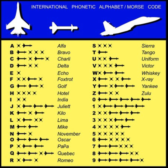
Many letters and phrases sound too similar, for example, the letters “p” and “b” may sound the same over the radio. So instead, pilots would say “papa” or “bravo”. Using the ICAO alphabet, pilots can communicate their location, approximate arrival time, any services required by crews, or the tail number of their plane.
All pilots, air traffic controllers, and flight dispatchers are required to know the aviation phonetic alphabet in order to more quickly and accurately relay information between each other. If a pilot needs to communicate information to the closest flight tower or to their destination, they will use the phonetic alphabet to avoid any confusion or miscommunication.
Today, the aviation alphabet is widely used and accepted and has become the standard for learning to become a pilot or work in the air travel industry. Understanding the words that are used for letters and numbers will help your communication be accepted no matter where you are traveling.
For example, pilots will not say a specific letter or number when speaking over their radio to dispatchers. They will instead say the word associated with the letters they are trying to communicate. The same is true for numbers. Instead of saying a specific number, the pilot or dispatcher will instead communicate each digit of the number separately.